Once you’ve learned the basics of the breadboard and components it’s time to build some Rad-fi kits.
Analog – Part A
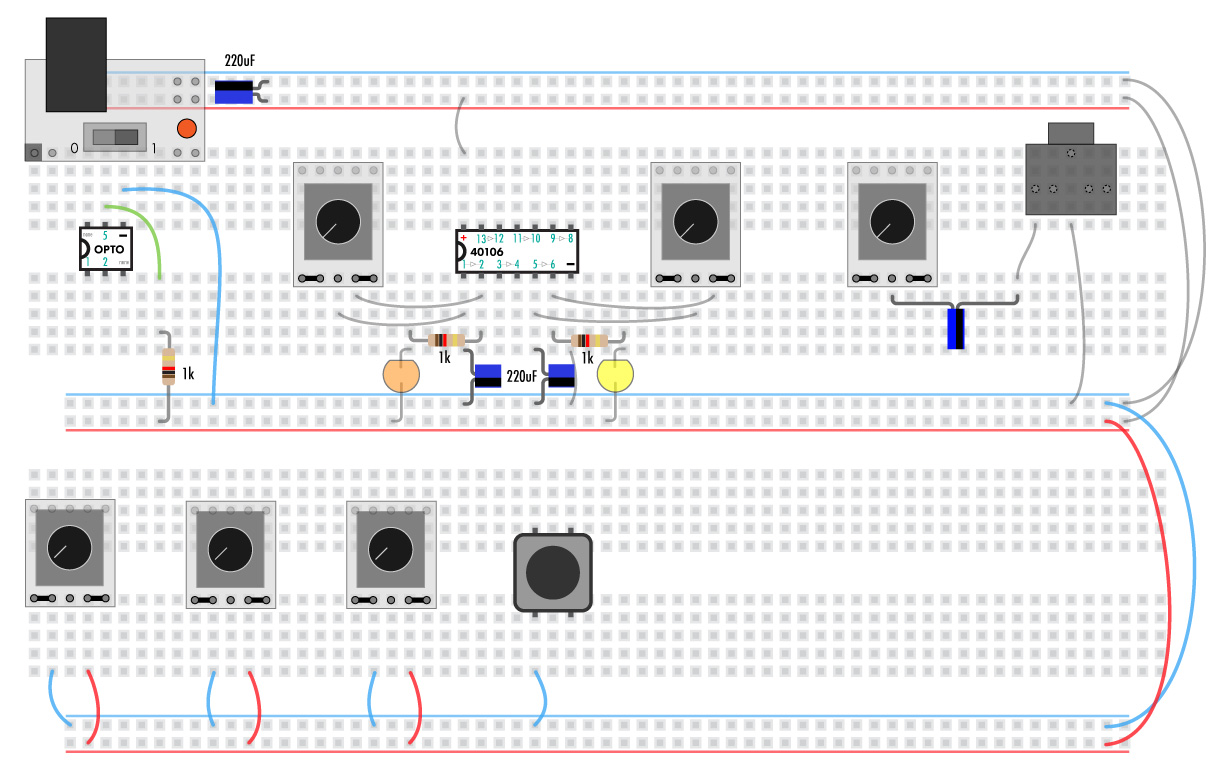
Here we’re going to make a two simple square wave oscillators square controlled by botentiometers.
Start with the power switch off and the battery or power adapter unplugged.
If you’re using your own power regulator make sure it’s outputting 5V and is connected correctly, with ground to the blue lines and +5 to red. Anything over 5V will damage the chips!
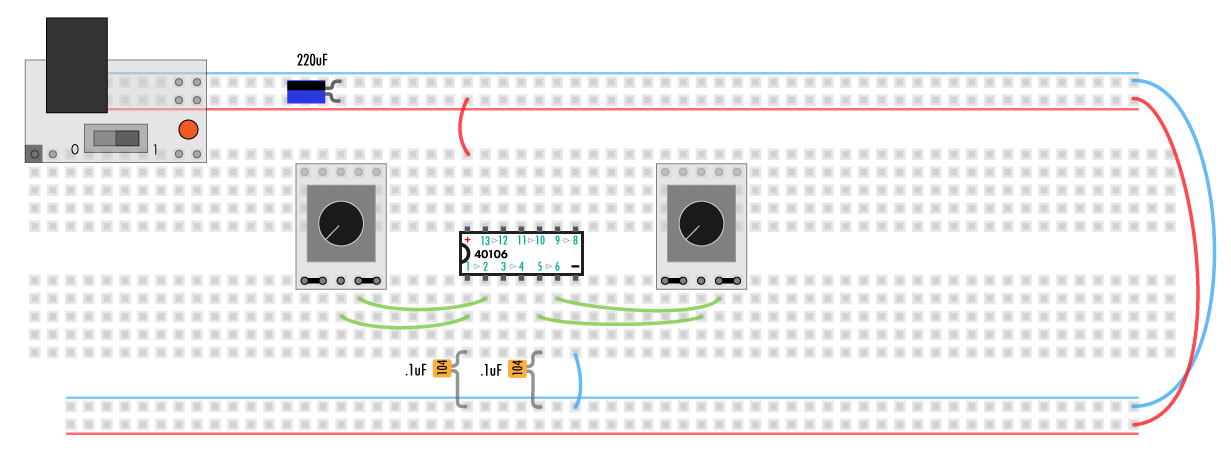
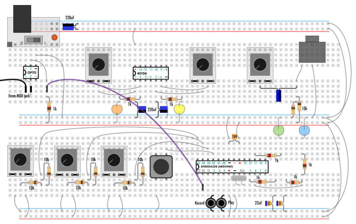
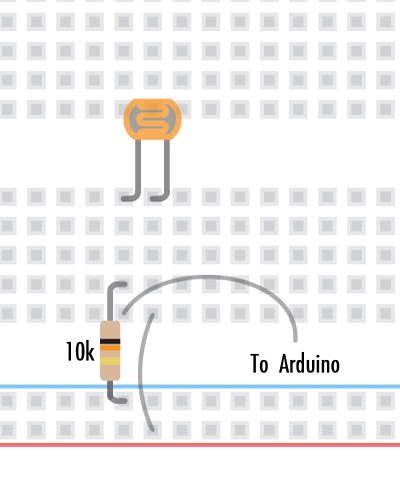
Add the 40106 chip, wires and caps as shown.
Blue and red lines indicate wires connected to +5V and ground. Green lines are other wires. Use any color of the solid wire you’d like but always go with the smallest one to fit the need.
Note that the cylindrical 220uF capacitors are polar, meaning that they need to go in a certain direction. The shorter lead on the same side as the black “-” stripe goes in the pad indicated.
The small ceramic capacitors can go in either direction.
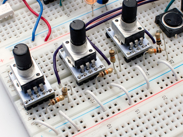
The two left pins and two right pins of the potentiometers are always connected as shown by the black lines on the pot’s circuit board.
Here it’s illustrated by the blue, green and purple lines.
None of the pins on the other side of the pot are connected to anything. They are just there for stability.
General placement of all the components is not super critical as long as they are connected correctly.
If everything’s shifted left or right a couple pads you’ll be fine. Follow along as close as possible though so you don’t run out of space later on.
////////////////////////////////////////////////////////////////////////////////////////////////////////////////////////////////////////////////////////////////////////////////////////////////////////////////////////////////////////////////////////////////////////
Analog – Part B
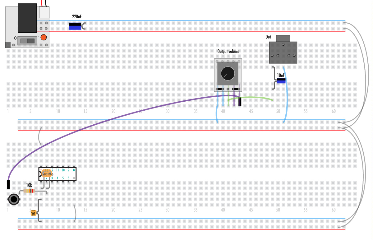
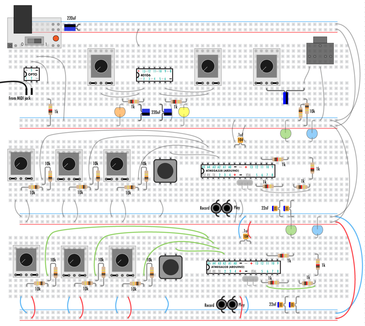
Now we’ll add the output jack and mix pot
The 10uF cap is polar and must go in the correct direction.
The 1/8” jack’s pins are hidden underneath.
Wires from the previous steps will be grayed out.
The purple wires are the pinned wires. These are easier to move around.
The pot on the right will allow you to mix the two oscillators but not change their volume.
If you need to add a volume pot you can put one in between the 10uF cap and resistors and the jack. See this step of the Rad-Fi Delay for an example.
Before turning on the power double check everything is in correctly, especially the power and ground wires.
Wiring a chip backwards can easily heat it up very quickly and kill it.
The output will be very loud. Start with your amplifier turned all the way down. Do not use headphones.
You should hear some nice square waves controlled by the right two pots if all is working correctly.
If not, something is not connected correctly:
Troubleshooting
If there’s a burning smell or something is at all warm:
REMOVE THE BATTERY OR POWER ADAPTER IMMEDIATELY
The power supply might be shorted. Make sure the red and blue are not directly touching anywhere.
A chip’s power pins are wired backward or to the wrong pins. Chip might be very hot!
Light on the power supply not coming on:
Remove the power supply. If it’s still not lighting up it’s the battery or power adapter.
Check the power wires. Make sure the red and blue are not directly touching anywhere.
A chip’s power pins are wired backward or to the wrong pins. Chip might be very hot!
No Sound/light/anything else:
Most probably something is not connected correctly. Usually it’s just a wire being shifted left or right and not on the correct column.
Check the power wires on the right.
Check that the polar component are the correct direction.
Double check every connection. Don’t be afraid of starting over.
////////////////////////////////////////////////////////////////////////////////////////////////////////////////////////////////////////////////////////////////////////////////////////////////////////////////////////////////////////////////////////////////////////
Analog – Part C
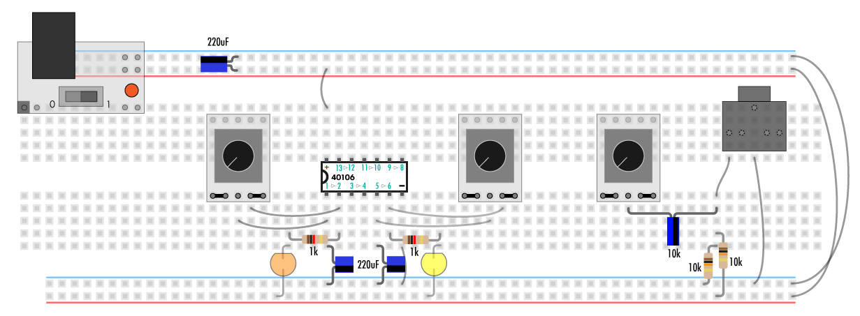
For the patchable synth we need the oscillators to be much slower so lets swap out the caps for much larger ones. (More about this in the hacking guides)
LEDs are added to make the oscillators visible.
Like all diodes, LEDs are polar. The short lead on the same side as the notch needs to go into the row with the 1k resistor. The long lead goes into the positive rail.
////////////////////////////////////////////////////////////////////////////////////////////////////////////////////////////////////////////////////////////////////////////////////////////////////////////////////////////////////////////////////////////////////////
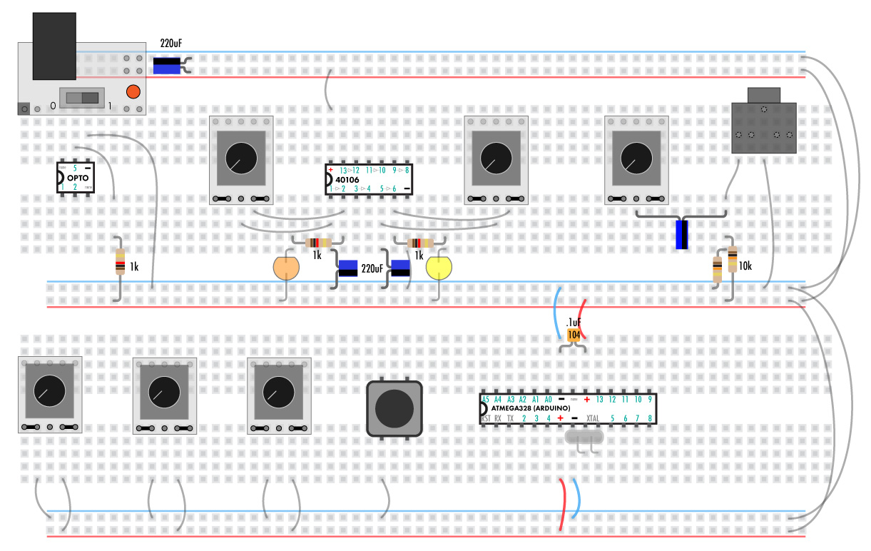
Digital – part A
First we’ll add the optoisolator. This chip takes the external MIDI signal and turns it into something the ATMEGA328 can read.
Add the 3 pots and button as shown.
////////////////////////////////////////////////////////////////////////////////////////////////////////////////////////////////////////////////////////////////////////////////////////////////////////////////////////////////////////////////////////////////////////
Digital – part B
Now it’s time for the ATMEGA328. This chip has been programmed with the lo-fi delay code using arduino (More info on the arduino delay addendum).
Note that the 328 has two sets of power and ground pins.
The crystal (XTAL) is not polar. If any wires or components touch it will cause the 328 to crash. If this happens don’t worry, just cycle the power.
////////////////////////////////////////////////////////////////////////////////////////////////////////////////////////////////////////////////////////////////////////////////////////////////////////////////////////////////////////////////////////////////////////
Digital – part C
Resistors and caps are next.
Make sure you have them in the correct rows before moving on to the next ones.
the 22nF caps have blue dots on top as it’s pretty hard to read the numbers on the side. This is something we have done to make it easier and is not a standard component marking.
Press the buttons down all the way so they are flat against the board.
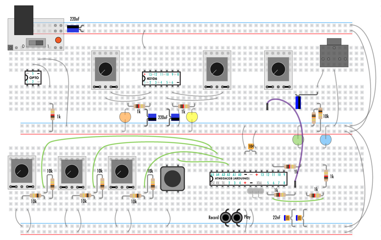
Clip the leads of the 10ks to keep things neat and low.
Now that the first 328 is in it’s time to test it out.
Insert the pinned wire as shown.
You should hear the synth change pitch with the left pot, amplitude with the middle, and shape with the right pot.
The green LED should “breath” and the blue led should blink when the amplitude is up.
The orange and yellow LEDs should blink at rates controlled by the pots near them.
If this is not the case refer to the troubleshooting guide.
////////////////////////////////////////////////////////////////////////////////////////////////////////////////////////////////////////////////////////////////////////////////////////////////////////////////////////////////////////////////////////////////////////
Digital – part D
The last step is to duplicate the digital synth on the bottom breadboard.
////////////////////////////////////////////////////////////////////////////////////////////////////////////////////////////////////////////////////////////////////////////////////////////////////////////////////////////////////////////////////////////////////////
Digital – part E
Lets take it for a more in depth test
Add pinned wires as show and turn the pots to these approximate locations
The purple wires are from the audio outputs of both synths. The pot they connect to mixes them together.
The synth in the middle will have a lower pitch, constant amplitude, and will be modulated by the yellow LED oscillator attached to it’s octave up input.
The synth at the bottom will have a higher pitch and will be triggered by the orange oscillator.
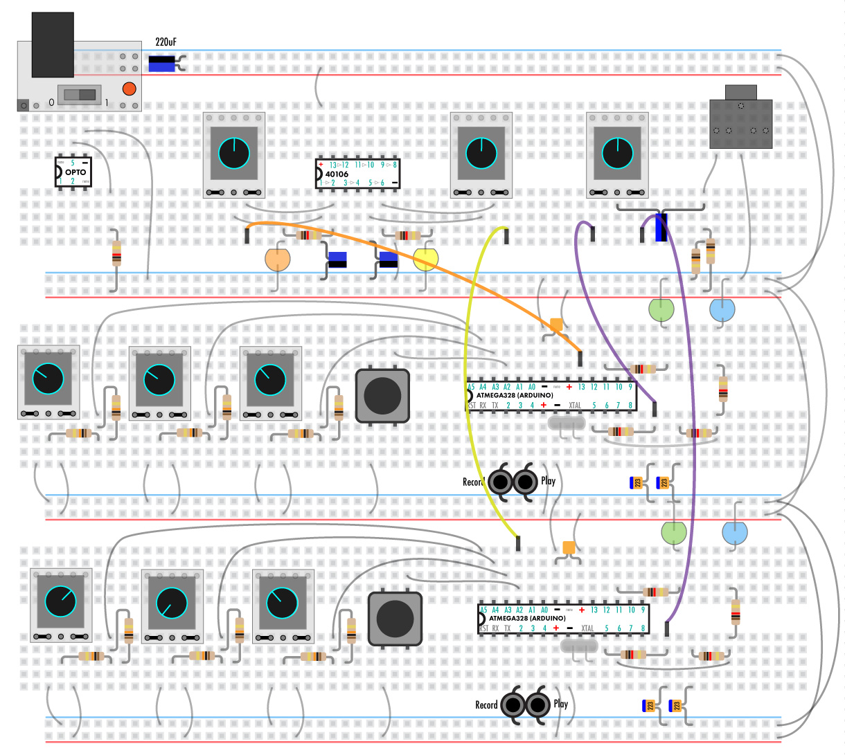
It should sound something like this when you’re done.
If something isn’t working then double check all of the connections and refer back to the troubleshooting section.
If you’re using MIDI connect the MIDI dongle and the pink pinned wire as shown. Note that the MIDI dongle you received might not have a black wire but it will have a white one which will go on the right side. (Inside the MIDI dingle the white wire is connected to pin 5 of the DIN connector and black is connected to 4).
The synth it’s connected to will get it’s pitch and amplitude information from the MIDI information sent on channel 1. The pitch and amplitude knobs can still adjust it up and down. More in the the MIDI implementation guide.
////////////////////////////////////////////////////////////////////////////////////////////////////////////////////////////////////////////////////////////////////////////////////////////////////////////////////////////////////////////////////////////////////////
User guide
The patchable synth has a ton of patch points.
Inputs are blue circles, outputs are red.
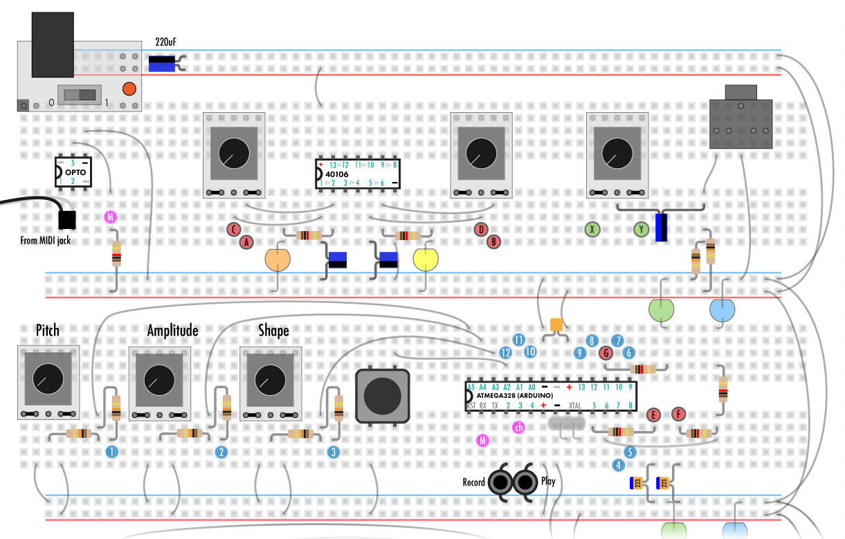
40106 Outputs:
A & B – Square wave outs. LEDs indicate when they are high.
C & D – The 40106 also puts out a triangle wave on the input pin (see more in the modification guide). The amplitude is low and it’s unbuffered but it’s still useful as a modulator.
Synth outputs:
E – Main audio out.
F – LFO out. By default this outputs different waveforms than the audio out and at much lower speeds but both are controlled by the same pitch, amplitude, and shape analog inputs. Input 13 changes the rate so it’s only about half the speed that of the audio out. Input 14 keeps the amplitude at full level regardless of what the amplitude input is doing.
The blue LED blinks along with the LFO out
The green LED is a status light. If it’s “breathing” the chip is powered correctly. When fully bright the device is in record mode. Blinking quickly means it’s playing back (more into in “sequence recording”). “G” can be used as a noisy output for modulation.
Synth Analog inputs:
1 – Pitch. This pot and input control the pitch of the oscillator.
2 – Amplitude. This pot and input control the volume level. When the are past half way the waveform is folded back to create more high frequency content.
3 – The shape of the output waveforms can be varied here. The audio out uses bandlimited waveforms that are designed to sound smooth but interesting in a lo-fi synth. The LFO puts out traditionals waveforms that are great as modulators but sound a little raspy over 500Hz.
Each input has two 10k resistors so that while a “CV” signal is coming in the pot can be used to adjust it.
4 – Dual voice octave – When low the audio out will have a second voice that is an octave lower.
5 – Dual voice detuned- When low the audio out will have a second voice that is about 50 cents out of tune.
If both pins are low the second voice will be 2 octaves down.
6 – Digital combine mode. This is a noise mode that changes the way the VCA works.
7- Sample & Hold – When low the vco input will have no effect and it will stay with the last reading. Try attaching a square wave to this pin and a slow triangular to the VCO to get some nice sci-fi random beeps.
8 – Octave up. When low the pitch is doubled.
9 – Octave up. When low the pitch halved.
When both are low the pitch is multiplied by two (Two octaves up).
10 – When low the LFO output is at full amplitude and is not affected bu the amplitude input.
11- When low the LFO output is much faster.
12- Envelope trigger. When low the amplitude will rise and fall in a musical way. This has the effect of the trigger button acting like a single key keyboard.
If the amplitude knob is at more than 0, this envelope will be added to the amplitude.
Sequence recorder.
Record/Play – Hit record to start recording the VCO pot and envelope button. The blue light will be steady on. Press record again to stop.
Play will blink the blue LED and playback the phrase. The VCO pot will adjust the pitch.
////////////////////////////////////////////////////////////////////////////////////////////////////////////////////////////////////////////////////////////////////////////////////////////////////////////////////////////////////////////////////////////////////////
MIDI
Connect The midi dongle to the opto and the two pink “M” pints together to allow the synth to receive MIDI data. Once the synth gets a midi signal the VCO and VCA input will only adjust the external signal. Reset the device to get it back to normal. Both synths can be attached to the otp to get the same MIDI data.
The pink “ch” pin changes the MIDI channel.
If this pin is unconnected when the device turns on the device will receive MIDI channel 1. If it’s low it will only read channel 3.
Note data is translated to pitch with the pitch pot being able to shift it up and down. If the pitch pot is in the middle it’s the exact note being sent.
The amplitude knob adds to the received velocity data.
If no note info is being received the device will be silent or on with the last note received. To get out of this mode reset the synth (power cycle or ground pin 1 “PST”).
MIDI CC # 22
This CC sets if the device is amplitude is set by the internal trigger enveloper or external MIDI velocity information.
When set high this cc turn off the MIDI control of amplitude. MIDI velocity info will have no effect on the amplitude of the device meaning the amp knob will act like normal. Each not will trigger just like the trigger button does.
When set low the devices amplitude is controlled by MIDI velocity information.
CCs 20 and 21 control the internal enveloper:
MIDI CC # 20
Trigger attack length
MIDI CC # 21
Trigger attack release
////////////////////////////////////////////////////////////////////////////////////////////////////////////////////////////////////////////////////////////////////////////////////////////////////////////////////////////////////////////////////////////////////////
Usage, tricks and more
There’s really no right or wrong way to patch the device. Any output can go to any input. If you want an input to stay “on” connect it to the ground strip.
The only thing to avoid is connecting outputs directly to the power stips and the xtal.
There are 4 triggers left open on the 40106. You can use them to buffer and flip external digital signals, like those coming from a modular, or you could make more oscillators with them.
External CV signals from your “real” modular can be used with the Rad-Fi patchable synth.
Simple 5V trigger signals can be buffered and flipped by one of the open schmitt triggers on the 40106 (the digital inputs are triggered when low).
For higher voltage analog CV signals you’ll have to make some kind of level shifter and attenuator as seen here.
The other way around is no problem. You can output signals from the Rad-Fi to pretty much any synth or modular.
Photocells can be used in place of potentiometers.
Wire the resistor to +5 and the photocell to ground to have it respond in the opposite direction. (Light high vs dark high).
See the analog and digital hacking guides for more info.
Have fun making noise!