Once you’ve learned the basics of the breadboarding it’s time to build some Rad-fi kits.
Analog – Part A
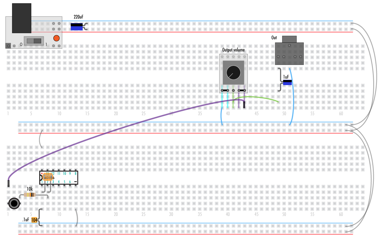
Here we’re going to make a single square controlled by a photocell.
Start with the power switch off and the battery or power adapter unplugged.
If you’re using your own power regulator make sure it’s outputting 5V and is connected correctly, with ground to the blue lines and +5 to red. Anything over 5V will damage the chips!
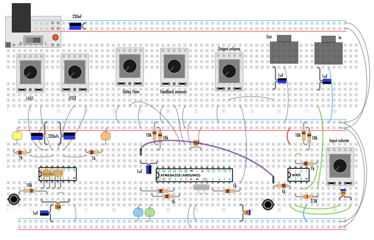
Add the 40106 chip, wires and cap as shown.
Blue and red lines indicate wires connected to +5V and ground. Green lines are other wires. Use any color of the solid wire you’d like but always go with the smallest one to fit the need.
Note that the cylindrical 220uF capacitors are polar, meaning that the shorter leads on the same side as the black “-” stripe go in pad indicated
General placement of all the components is not super critical as long as they are connected correctly.
If everything’s shifted left or right a couple pads you’ll be fine. Follow along as close as possible though so you don’t run out of space later on.

////////////////////////////////////////////////////////////////////////////////////////////////////////////////////////////////////////////////////////////////////////////////////////////////////////////////////////////////////////////////////////////////////////
Analog – Part B
Now we’ll add a photocell, resistor, small capacitor and button to the 40106 chip.
None of these parts are polar so they can go in either direction.
On the other side of the board a potnetiometer jack and capacitor are added.
This cap is polar and must go in the correct direction.
Note that the two left pins and two right pins of the pot are always connected as shown by the black lines on the pot’s circuit board.
Here it’s illustrated by the blue, green and purple lines.
None of the pins on the other side of the pot are connected to anything. They are just there for stability.
The 1/8” jack’s pins are hidden underneath.
Wires from the previous steps will be grayed out.
The purple wire is a pinned wire.
Before turning on the power double check everything is in correctly, especially the power and ground wires.
Wiring a chip backwards can easily heat it up very quickly and kill it.
Start with the volume pot turned all the way to the left. If you have something in wrong it could be VERY loud when the power is turned on.
Plug in some headphones (not on your head) or an amp (turned down low) and turn the power on.
Slowly turn the volume up. You should hear a nice square ware controlled by the photocell.
Note that I change the capacitor out for a .1 to a 1uF as the photo lights are so bright.
If not, something is not connected correctly:
Troubleshooting
If there’s a burning smell or something is at all warm:
REMOVE THE BATTERY OR POWER ADAPTER IMMEDIATELY
The power supply might be shorted. Make sure the red and blue are not directly touching anywhere.
A chip’s power pins are wired backward or to the wrong pins. Chip might be very hot!
Light on the power supply not coming on:
Remove the power supply. If it’s still not lighting up it’s the battery or power adapter.
Check the power wires. Make sure the red and blue are not directly touching anywhere.
A chip’s power pins are wired backward or to the wrong pins. Chip might be very hot!
No Sound/light/anything else:
Most probably something is not connected correctly. Usually it’s just a wire being shifted left or right and not on the correct column.
Check the power wires on the right.
Check that the polar component are the correct direction.
Double check every connection. Don’t be afraid of starting over.
////////////////////////////////////////////////////////////////////////////////////////////////////////////////////////////////////////////////////////////////////////////////////////////////////////////////////////////////////////////////////////////////////////
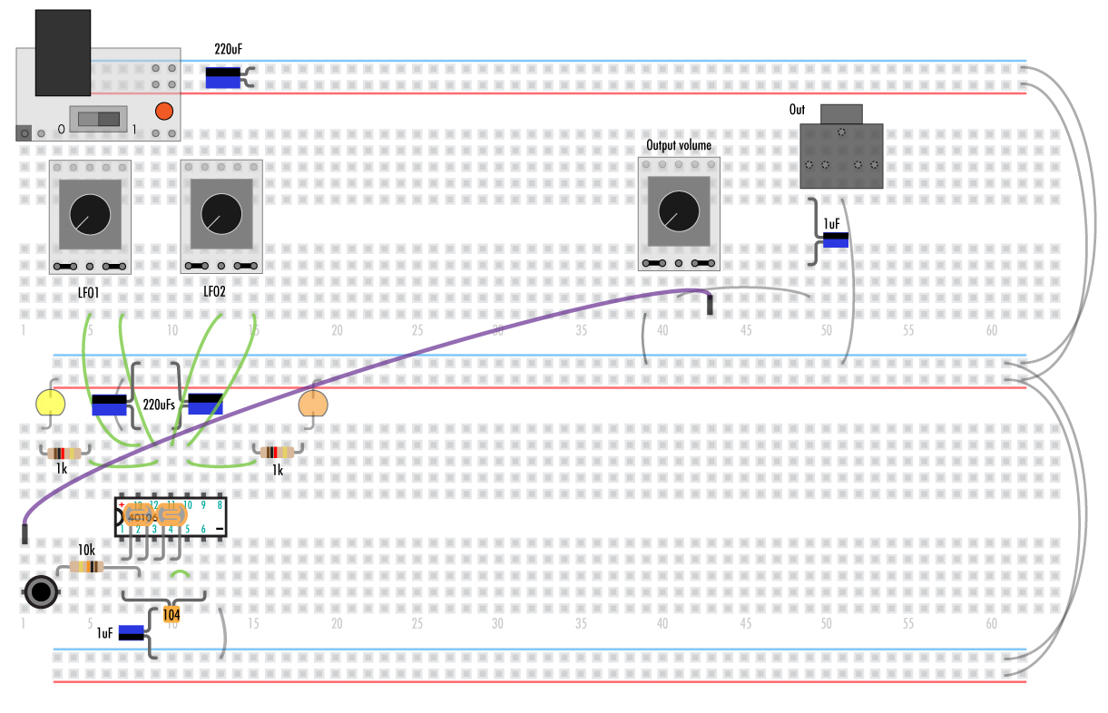
Analog – Part C
Here we’ll add and change some more components on the 40106.
The left photocell will control modulating and the right will be pitch. By connecting a capacitor between oscillator ins and outs instead you can make one modulate the other.
This chip is a Hex Schmitt trigger. It’s capable of making 6 oscillators with just a resistor and capacitor for each. (More info in the 40106 addendum.)
Notice that the capacitor on pin 1 of the 40106 has changed to a polar 1uF.
On the top of the chip we’ll make some LFOs to modulate the delay.
////////////////////////////////////////////////////////////////////////////////////////////////////////////////////////////////////////////////////////////////////////////////////////////////////////////////////////////////////////////////////////////////////////
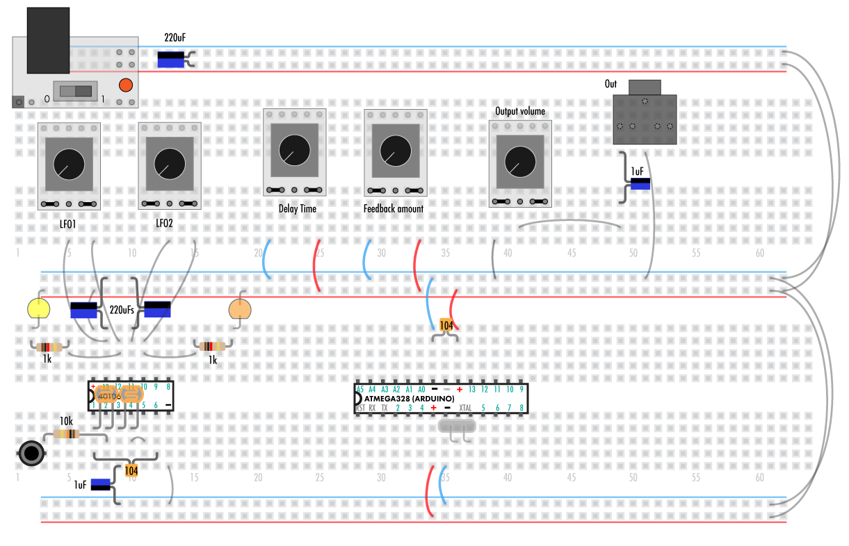
Digital – part A
Now it’s time for the ATMEGA328. This chip has been programmed with the lo-fi delay code using arduino (More info on the arduino delay addendum).
Note that the 328 has two sets of power and ground pins.
The crystal (XTAL) is not polar. If any wires or components touch it will cause the 328 to crash. If this happens just cycle the power.
////////////////////////////////////////////////////////////////////////////////////////////////////////////////////////////////////////////////////////////////////////////////////////////////////////////////////////////////////////////////////////////////////////
Digital – Part B
Add the rest of the parts and wires to the 328.
Purple pinned wire connects the output of the photocell synth to the input of the delay.
The delay time pot controls how long the delay is. The blue LED should blink with the delay time.
The feedback controls the amount of the effect. It goes infinite when the knob is around 3 o’clock and insane after that.
Double check that the 328 is wired to ground and +5 correctly before turning on the power.
If something is not working, refer back to the troubleshooting section.
Your device should now sound something like the first part of this video:
////////////////////////////////////////////////////////////////////////////////////////////////////////////////////////////////////////////////////////////////////////////////////////////////////////////////////////////////////////////////////////////////////////
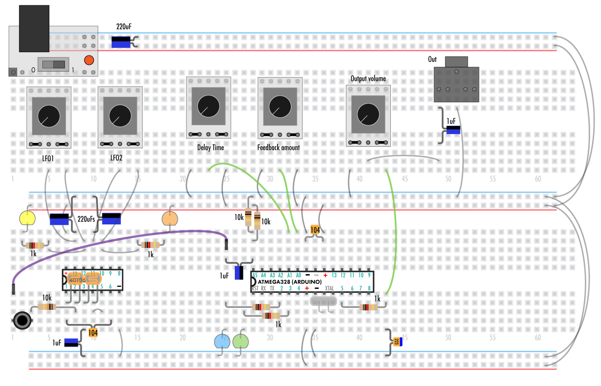
Digital – Part C
Let’s add an audio input.
The 6002 chip is an op-amp that will amplify the incoming audio signal to something the 328 chip will like.
Notice that the capacitor attached to the new input jack is going the opposite direction of the one on the output.
Now the purple wire is connected between the delay input and a button that lets the incoming audio signal pass.
////////////////////////////////////////////////////////////////////////////////////////////////////////////////////////////////////////////////////////////////////////////////////////////////////////////////////////////////////////////////////////////////////////
User Guide
Now that all the parts are in you can get to experimenting. Don’t be afraid to connect any output to any input!
The only way you can hurt the chips is by directly connecting 5V to ground or mixing up + and – pins. Attaching anything to the XTAL pins will crash the delay but not damage it. The RST pin resets the 328 when low.
To turn a pin “on” just connect it to ground.
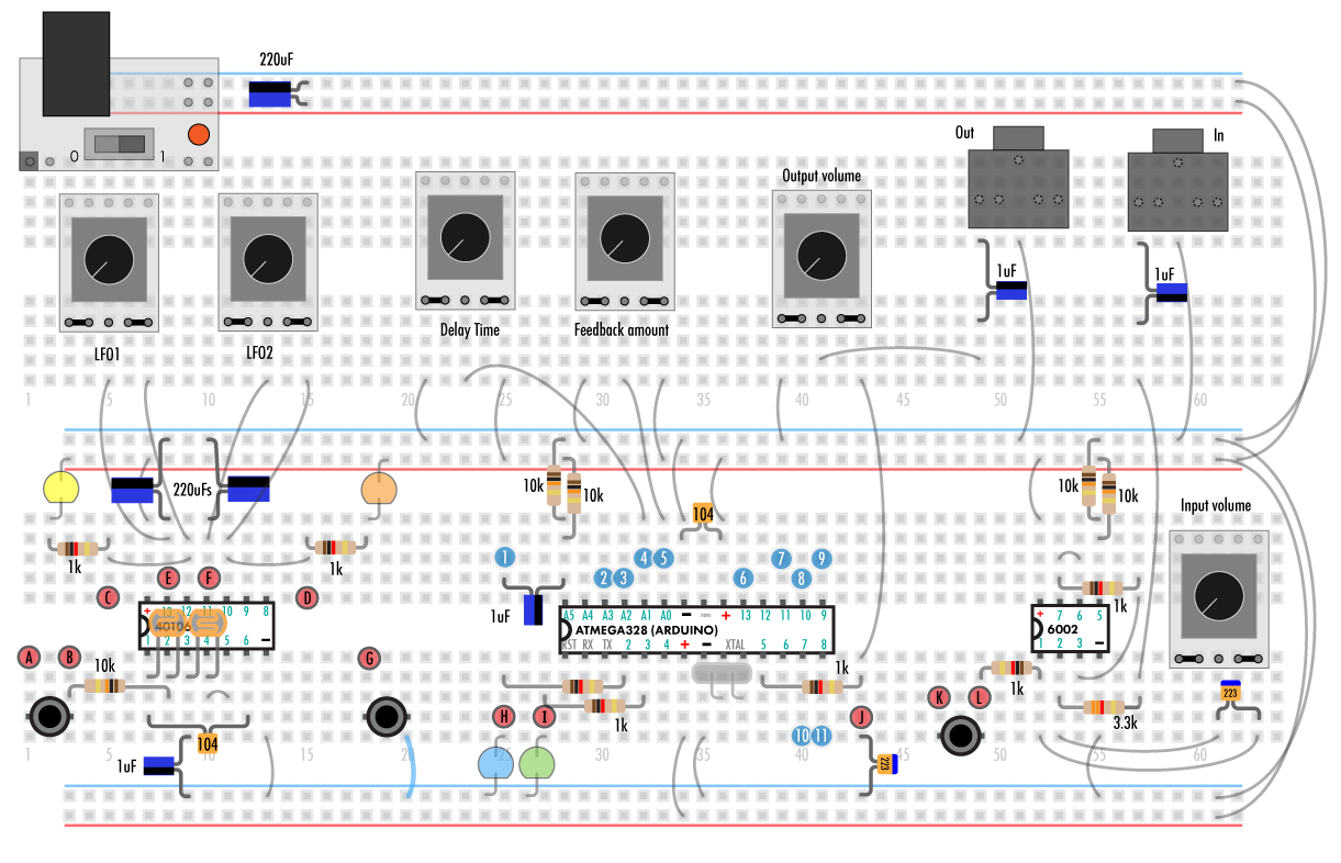
Outputs (Red circles)
A – Photocell synth output button
B – Photocell synth output
C – LFO1 out
D – LFO2 out
E – LFO1 in
F – LFO2 in
The LFo inputs can be used to syn the ocillarots together as seen in the photocell synth but they also ouput a triangular wave. It’s at much lower amplitude and hooking it to some sources can kill the oscillation but it’s useful as a modulator as it triggers 1/2 of a period after the square wave does.
G – Button. This one’s an example. Tie it to an input, like freeze, to activate it manually.
H – Delay time pulse. The LED is useful for playing the photocells but it can also be attached to any input pin.
I – Audio LED. This blinks when the audio peaks.
J – Delay output
K – Amplified external audio button
L – Amplified external audio
Inputs (Blue circles)
1 – Delay audio input
2 – Sample rate bit 1
3 – Sample rate bit 0
2 high 3 high – The sample rate can be controlled by two pins. When both pins have nothing connected or are tied to a high signal the sample rate is ~14kHz. Changing this does not affect the delay length.
2 high, 3 low – 14k/4 = 3.5 kHz sampling rate
2 low, 3 high – 14k/6 = 2.3 kHz
2 low, 3 low – 14k/8 = 1.75 kHz
4 – Delay time analog input
5 – Feedback amount analog input
Digital signals can be applied to the pins as well.
6 – Bypass – When low only the audio input going into the delay is muted. You’ll have the trailing end of the delay then just the dry audio coming in.
7 – Modulate – When low the delay time goes up and down at a rate determined by the delay time pot.
8 – Reverse. Reverses the delay playback. Especially useful with freeze, not so much with short delay times.
9 – Freeze – loops whatever is in the delay buffer over and over. The delay time pot controls the end point of the loop.
10 – Delay time bit 1
11 – Delay time bit 0
10 high 11 high – When both pins have nothing connected or are tied to a high signal the delay sample rate is ~14kHz and is ~120 milliseconds long.
10 high, 11 low – 14k/2=7kHz sampling rate, 240mS delay length. The length is doubled and the bitrate is halved
10 low, 11 high- 14k/3=4.3kHz 360mS
10 low, 11 low- 14k/4=2.1kHz 480mS
Usage, tricks and more
No input – When the feedback knob is past 3 o’clock the device will start making noise without input. Turn down the input and try very small changes in the delay time and feedback knob. Sounds best when the delay time inputs are both low.
LFOs to multiple inputs – You can split outputs to multiple inputs. Try patching one LFO to freeze and a delay time input.
LFOs to delay time and feedback. – Try putting a resistor, pot, or trim pot between an LFO and the feedback or delay time pin on the 328.
Photocells can be used in place of potentiometers.
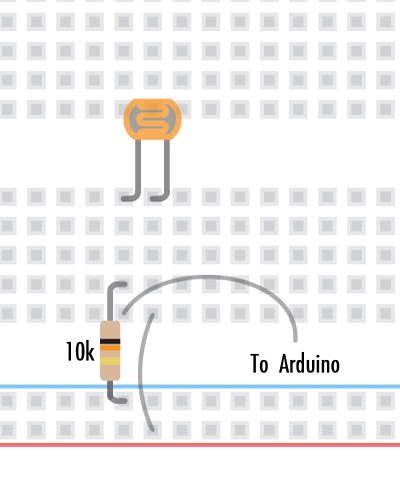
Wire the resistor to +5 and the photocell to ground to have it respond in the opposite direction. (Light high vs dark high).