The breadboard
This guide is an introduction to the Rad-Fi system and covers the basic use of the breadboard.
A breadboard allows you to design and test circuits by plugging components into a standard .1” grid.
This allows you to quickly and easily make an modify circuits without soldering them together.
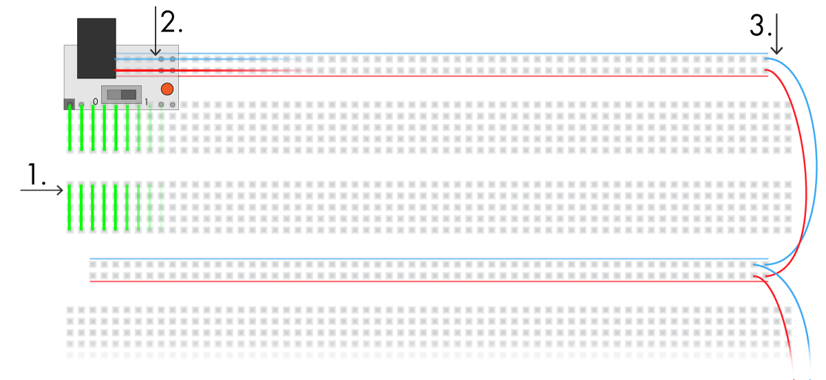
1. Each column of five is connected vertically as shown here with green lines
2. The horizontal blue and red row are all connected.
3. By putting wires between them and attaching the power supply to the top left corner all the points on the red row become connected to +5v and blue gets connected to ground.
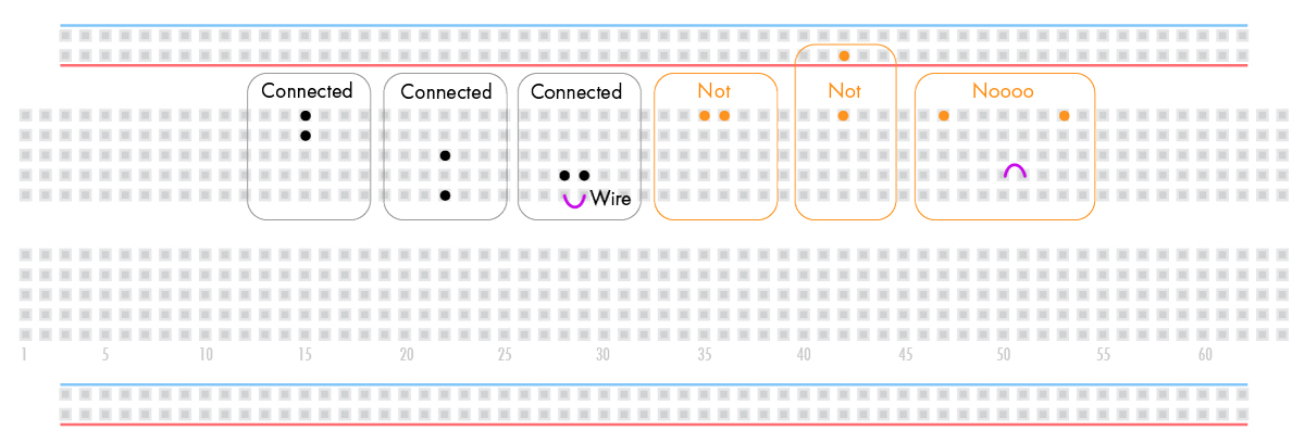
All columns of five are connected vertically, never horizontally. The power rows are connected horizontally. Here are a few examples.
////////////////////////////////////////////////////////////////////////////////////////////////////////////////////////////////////////////////////////////////////////////////////////////////////////////////////////////////////////////////////////////////////////
Components
Here’s an overview of the parts used in the Rad-Fi kits.
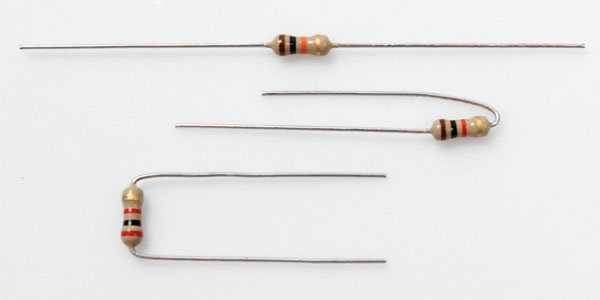
Resistors
limit the flow of current. The are measured in Ohms which are indicated by the colored stripes. You won’t have to decipher them for Rad-Fi kits but it is helpful to know how to read the color codes (or just use Wolfram to do it).
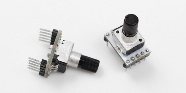
Potentiometers
are variable resistors. They increase resistance between the middle and right pins as you turn clockwise, decrease it between the middle and left, and vice versa counterclockwise.
The potentiometer has its own little circuit board to make it easy to use on a breadboard. All of the ones included with this kit are 20 kOhm.
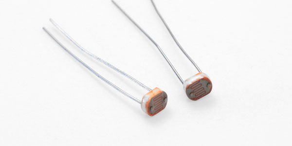
Photocells
are also variable resistors but they change based on the amount of light hitting them. More light, lower resistance.
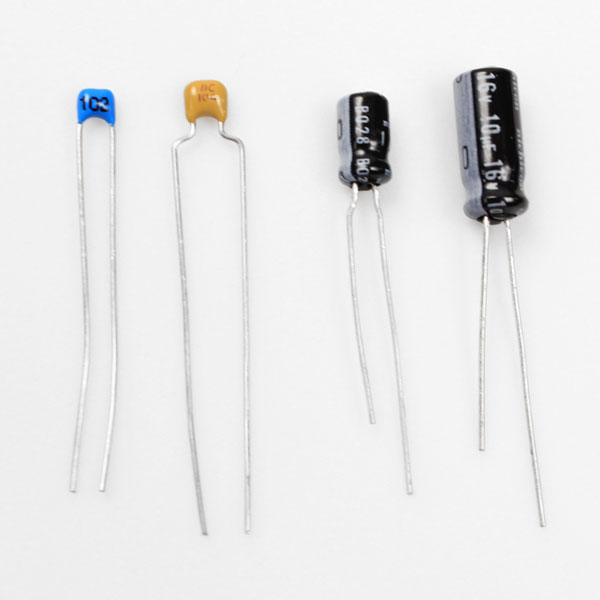
Capacitors
can store and filter current. They allow changing current to pass but not static current.
Ceramic caps, the two on the left, are non-polar meaning that they can be used in either direction. The value is marked on the side in a simple code (104 = .1 uF [microfarad]; 102 = 1 nF [nanofarad]).
Electrolytic caps, on the right, are polar with the negative side marked with a stripe and a smaller leg. The value is marked on the side directly.
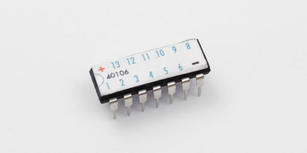
ICs aka Chips
Integrated Circuits are collections of tens to billions of components. There a jillions of types of chips but we’ll be focusing on simple and analog ones, the op-amp and hex schmitt trigger, and the ATMEGA328, the chip used by the Arduino UNO.
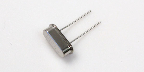
Crystal oscillator
Like the name suggests, this contains a magic crystal the oscillates at a very specific frequency. It’s used to clock the Arduino chip.
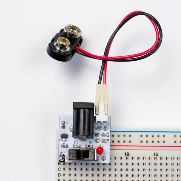
Rad-Fi power regulator
Most circuits need a specific regulated voltage to operate and is usually the first point of failure in a circuit. It it’s hooked up incorrectly it can damage itself and the circuit it’s attached to.
The Rad-Fi power regulator removes this issue and makes it easy to start making noise.
This circuit board takes the power from a 9V battery or power supply and regulates it to 5V, making it usable by the ATMEGA328.
The far left pin puts out 9V. Hooking 9V directly to the ATMEGA328 or will damage it.
The regualtor in your kit might look like this:
Or like this:
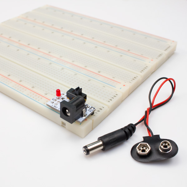
Both work just the same.
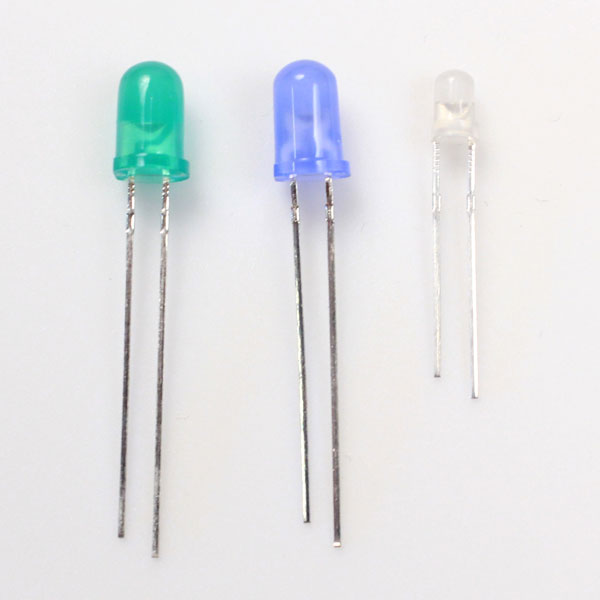
LEDs
produce light when current is passed through in the correct direction. Make sure not to connect them directly to the power supply as anything over 3 Volts will damage them. Like any diode, current can only flow through it one way.
The cathode or negative lead is the shorter one, also marked by the flat notch on the side of the LED itself.
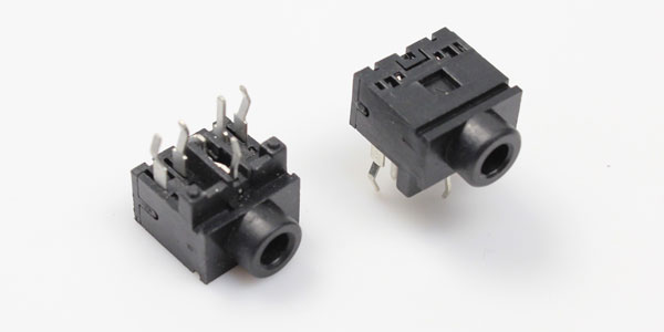
1/8” jack
headphone sized jack for inputting and outputting audio.
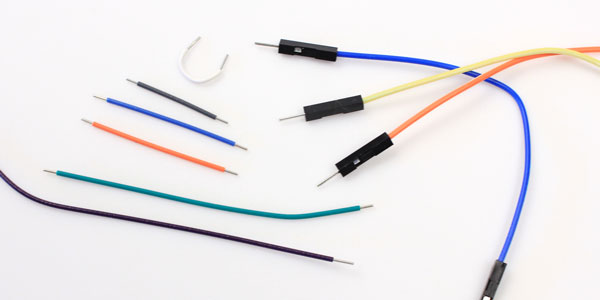
Wires
There are two types of wires included with this kit: solid and pinned wires.
The solid ones come in several sizes and are used for most connections. Always use the smallest wire that will fit your needs.
The wires with black plastic ends and pins are used for things that will be changed or are outside the breadboard.
They will be marked with purple and will be used in the later steps
In this guide they will be blue or red for power and green for everything else, while the actual IRL colors can be whatever you’d like.
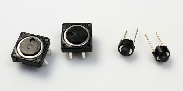
Buttons
This kit will use small buttons called tactiles. The pins on either side are only connected when the button is pressed. They do not latch like a switch.
////////////////////////////////////////////////////////////////////////////////////////////////////////////////////////////////////////////////////////////////////////////////////////////////////////////////////////////////////////////////////////////////////////
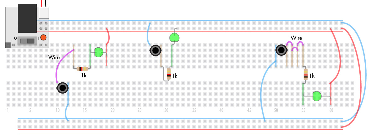
Your first circuit
Here we have a very simple circuit. The parts used are included with the delay and synth kits.
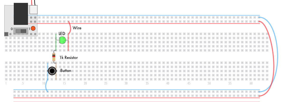
First make sure the power supply is in correctly and that the red line on the breadboard is on top.
Then make these connections:
The blue wire connects the ground to a column.
The short leg of the LED, here indicated with a notch in the circle, just like the actual LED, is put into the grounded column.
To other leg of the LED goes into a row along with a 1k resistor.
The Resistor’s other lead meets with a button.
And the button is tied to the +5v red row.
Press the button to light the LED.
If the light comes on you’ve got it! That’s all there is to breadboards. Connect the thing to the right thing. Repeat.
If the light isn’t coming on:
There’s a burning smell or something is at all warm.
REMOVE THE BATTERY IMMEDIATELY
The power supply is shorted. Make sure the red and blue are not directly touching anywhere
Is the light on the power supply not coming on?
Check the power wires.
Try a fresh battery.
Light is still not coming on?
Check that the LED is in the correct direction with the short lead connected to ground
Make sure that all pads that should be connected are vertically, not horizontally.
This same LED circuit can be wired any number of ways.
Each of these examples provides the same result. As long as the wires are connected, the placement is irrelevant.
Don’t be afraid to bend and cut leads to fit them in. Don’t cut them too short though as you might need them longer for other circuits.