Rad-Fi System central page.
This guide will get you started modifying the analog portions of the Rad-Fi kits.
The 40106

The 40106 Hex Schmitt Trigger (aka 74HC14N) is the basis of a lot of DIY noise projects. It contains six inverters that among other things can be used to make simple square wave oscillators with just a single resistor and capacitor.
Here’s a single oscillator.
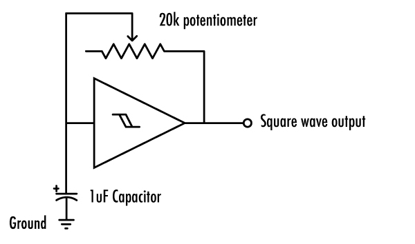
The input is attached to a capacitor that goes to ground and a resistor goes from the input to the output.
The bigger the capacitor or the bigger the resistance, the lower the pitch.
Here’s the light controlled oscillator used in the Rad-Fi Glitch Delay.
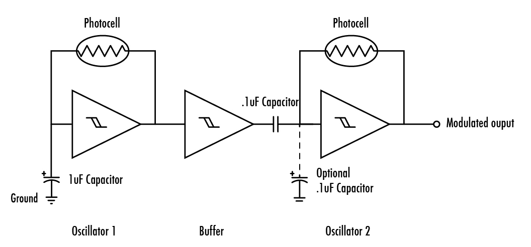
The oscillators are just the same except a photocell is used instead of a potentiometer.
The range of the photocell is about 500k Ohm to 10k Ohm. This is much larger than the 20k pot from the first example, so a much smaller capacitor is used.
The first oscillator goes through another trigger which acts as a buffer. The buffer’s output goes to a capacitor which attaches to the second oscillator’s input.
This makes the first oscillator turn the second on and off. Since the capacitor of the second oscillator is not grounded when the first oscillator is high it can’t oscillate.
Adding the optional cap will make it so the first oscillator makes the pitch of the second lower when it’s high as the send osc has it’s own capacitor.
Another way to get oscillators to interact is with a photocell and LED.
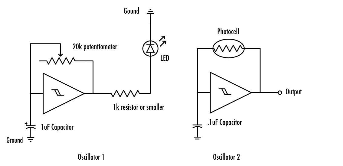
Like the Thingamagoop, or a vactrol, the LED can be pointed at the the photocell to change the pitch of the second oscillator.
In this oscillator you can change the duty or pulse width of the square wave.
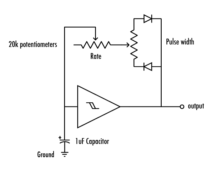
The pot on the right changes how the feedback flows through the two diodes which causes it to oscillate asymmetrically.
You can also get triangular waves out of a 40106
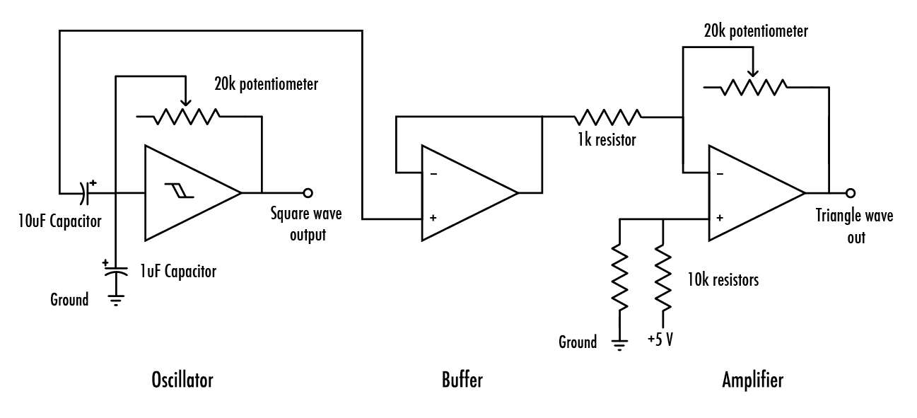
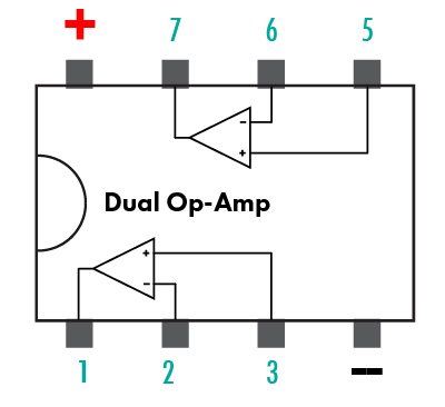
A rail to rail opamp, like the 6002 from the Glitch Delay kit, is necessary. Power it just like the 40106, between +5 and ground.
A capacitor is connected between the input of a simple 40106 oscillator and an opamp buffer. After the buffer there is a standard inverting amplifier. The two 10ks give the signal the correct offset but they can be replaced with a potentiometer (middle to +, left and right pins to +5 and ground) for some clipping effects.
The amplifier’s pot controls the volume. It will start to clip nicely after about halfway.
To clip the waveform off the top and the bottom of the rails replace the two 10ks going to ground and +5 with a pot.
With these simple oscillators you can build all kinds of noise makers!
Combine them using resistors or volume pots, diodes, LEDs…
The Op-Amp
We’ll be adding to this section soon.
In the meantime check out:
Texas Instruments Single Supply Op-amp Collection
LM13700 datasheet
Pico Paso schematics
Doepfer A-100 DIY and vactrol filter.
Analog resources
More info on the 40106 and other CMOS noise making chips and beyond.
Casper Electronics – OMSynth lab – More on the 40106
Beavis Audio – 40106 and other CMOS synths.
The Lunetta ebook – Lunetta is a collection of CMOS circuits that work together / a kind of DIY synth manifesto.
Forrest Mims Engineer’s Notebook – Mims’s books are the doorway into DIY electronics for a lot of people since the 70s.
He invented the stepped tone generator, aka the atari punk console, one of the most popular noise kits, he’s still active and we’re still drawing inspiration from his writings.
Hack-a-day has an ongoing series on making noise with logic chips.
More recomended reading on the Intro to DIY synthesis page.