In this guide you’ll learn how to make your own sensors to use with the Sensory Coupler.
Connecting Potentiometers
Connecting a device with two pins
Connecting ICs with analog outputs
The sensor jack on the SC is TRS with this pinout:
Tip – 3.3V
Ring – Analog Input
Sleeve – Ground
Any device that has an analog output and works at 3.3V can act as a sensor.
The analog input and 3.3V are protected but it’s best to not apply any voltages over 3.3V or under 0V to the Analog Input.
Don’t connect the 3.3V pin directly to ground or to any other voltage source.
This adapter from Adafruit makes connecting to the SC very easy. All you’ll need to use it is a small screwdriver.
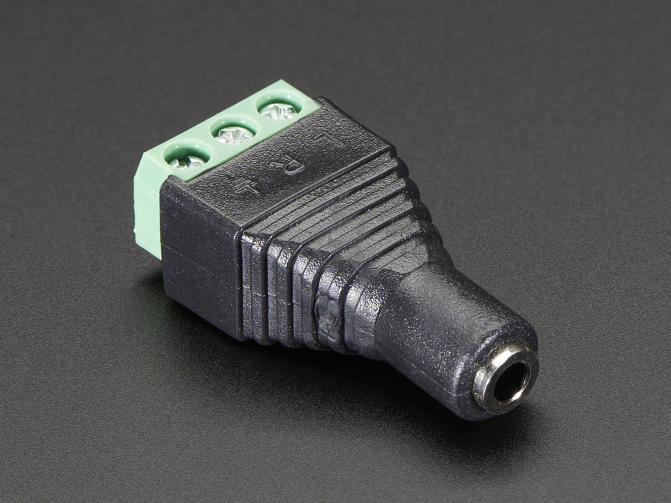
L is Tip, 3.3V
R is Ring, Analog Input
And![]() is the symbol for ground, the sleeve
is the symbol for ground, the sleeve
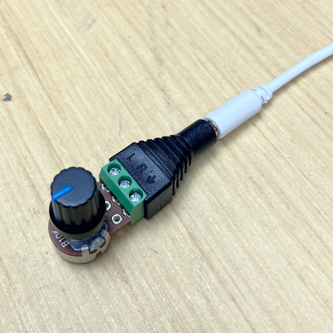
Connecting a potentiometer
A pot might not be the most interesting sensor at first glance but it’s useful to demonstrate how to connect devices.
This kind of potentiometer can screw directly into the adapter.
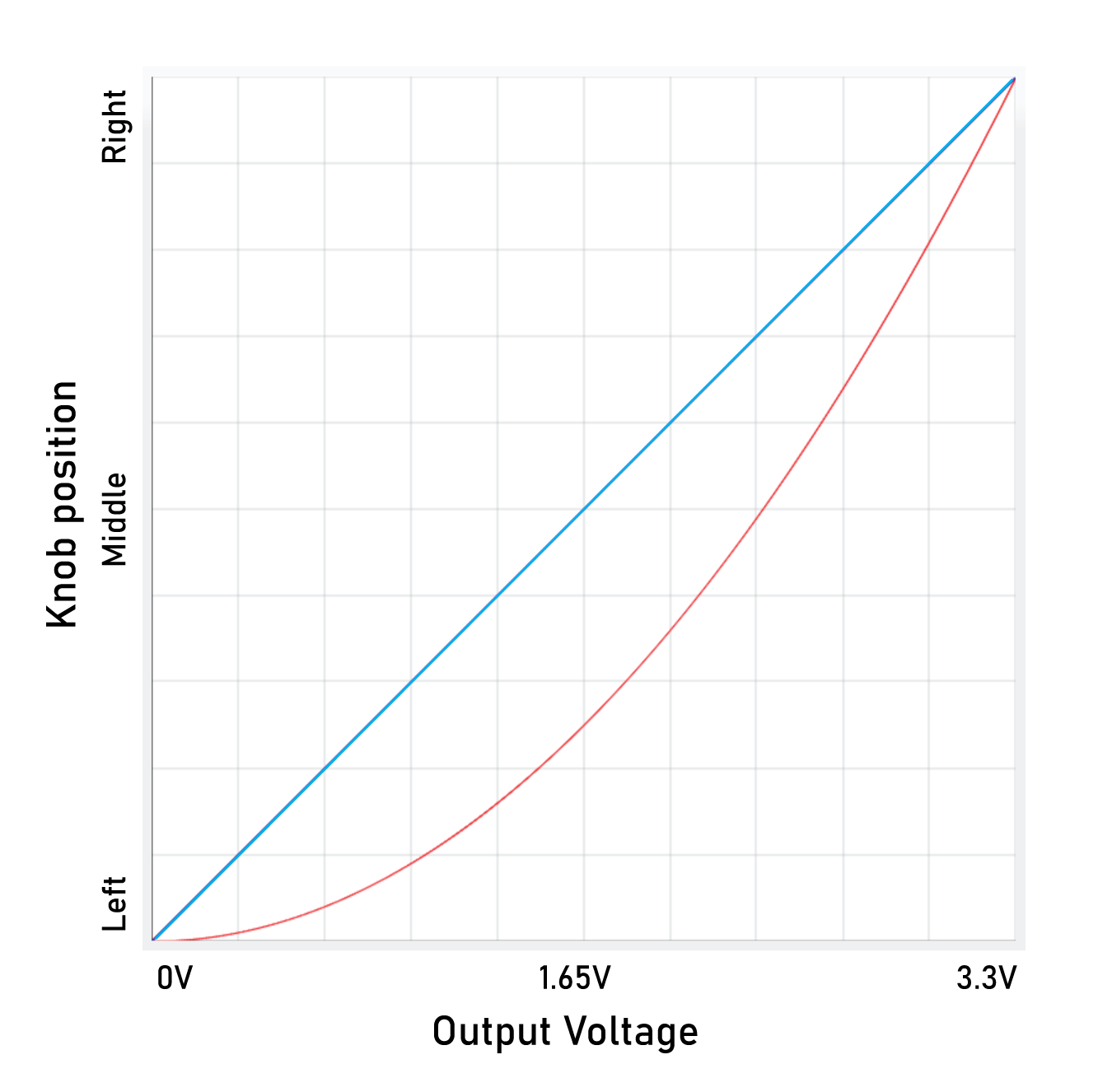
Any pot with a value between 10k-100k will work about the same. A linear pot will provide an output that looks like the line. Audio aka log is graphed in red.
If you flip the pot upside down in the adapter the output will be high, 3.3V, when the knob is turned fully left and 0V when turned to the right.
This works because the potentiometer is working as a voltage divider. As the resistance between the middle and left pins of the pot drop a you turn the knob to the left, the resistance between the middle and right pins increases.
One fun thing you could do with a potentiometer sensor is find a huge knob to put on it.
You could also connect expression pedals, the only trick is figuring out what pins they use for 3.3V, ground, and output.
But what if the sensor only has two pins?
Connecting a device with two pins
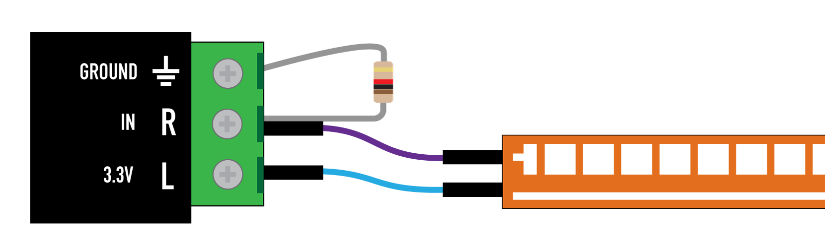
For devices like Photocells, Flex sensors, Pressure sensitive sheets, etc. you’ll also need a fixed resistor. You might try values between 1k to 100k ohms. Very little current will be going through them so any old resistor will work (1/8W, 1/4W etc).
A flex sensor is a single resistor that changes based on how much it’s bent. A single resistor can’t really change a voltage going through it so a fixed resistor is added to create a voltage divider. The flex sensor doesn’t fit into the adapter so pin to socket jumpers are used.
Resistors don’t have a polarity so it doesn’t matter how the flex sensors pins are attach as long as one of the goes to either 3.3V and ground and the other goes to “IN”. Just like on the pot, if you flip the fixed resistor and the sensor the response will be backwards. In the diagram I have it hooked up one way while in the picture it’s all flipped.
Ground – One side of a fixed resistor. In this example I’m using 1k.
IN – Other side of fixed resistor AND one side of the sensor
3.3V – Other side of the sensor
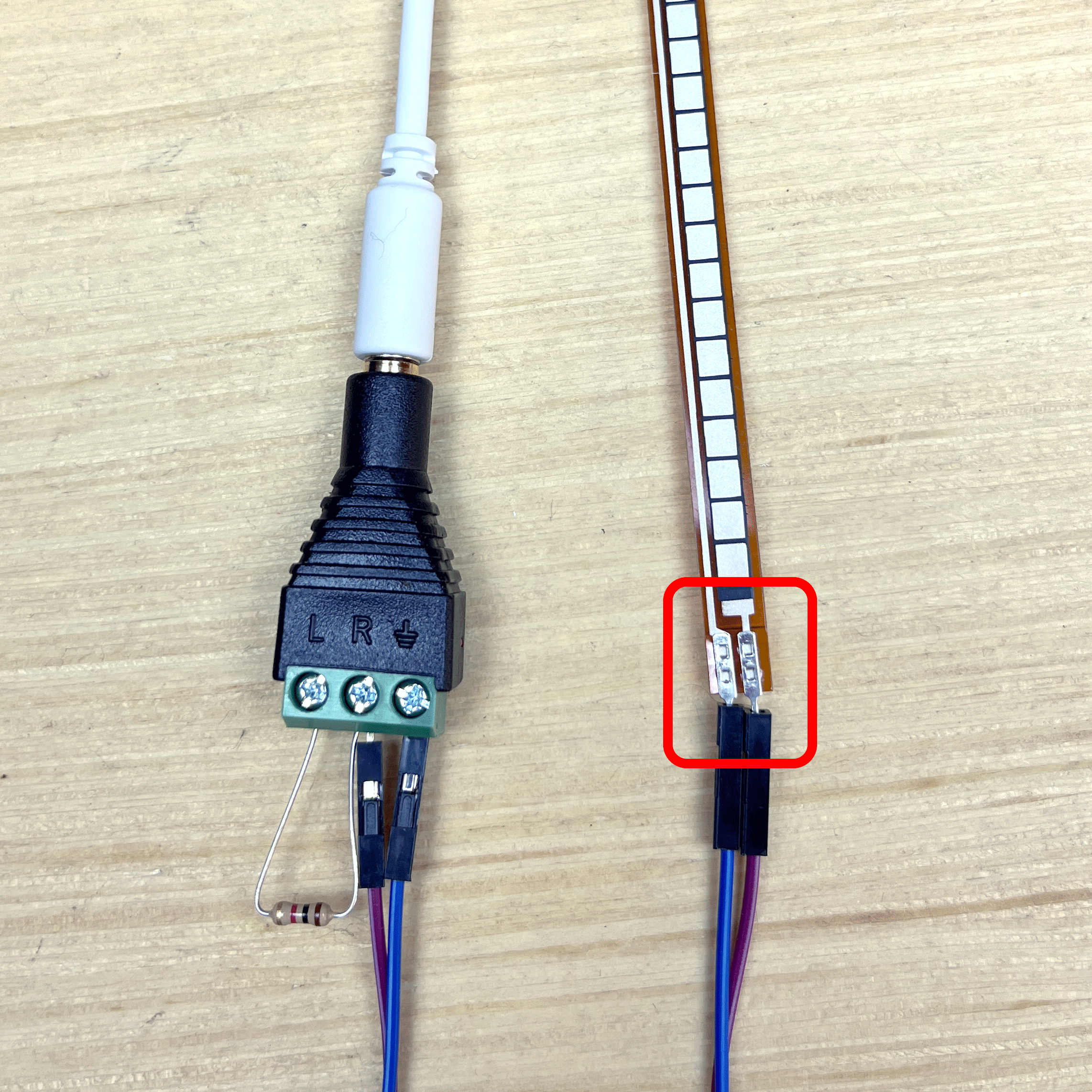
Don’t bend the area in the red box. The flex sensor is much more delicate at the pins connector end.
In this video I held it in a clamp to avoid stressing that section. The audio is coming from the Plaits.
This same method an be used for Photocells (try putting colored gels over them to filter out other colors), Pressure sensitive sheets, Piezo ribbons, anything that is a is a single variable resistor. This is how the included hall sensor and phototransistor work.
Connecting ICs with analog outputs
One other type of device that can be used are integrated circuits that have analog or PWM outputs. As long as the y can be powered by 3.3V they will probably work.
This temperature sensor is a good example.
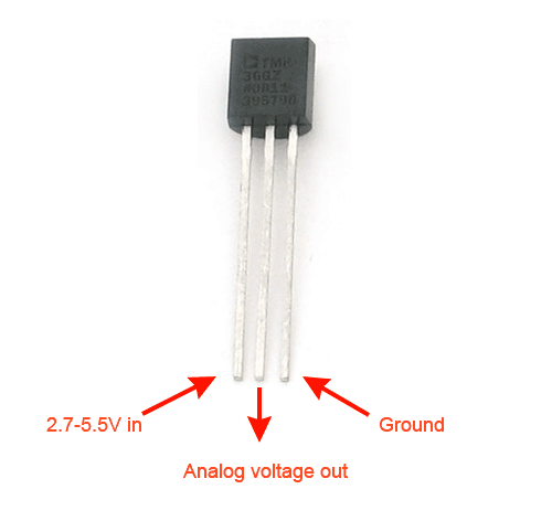
Ground goes to the pin on the right
IN goes to the middle pin
And 3.3V connects to the first pin
Calibrating a temperature sensor might be a little tricky but I was able to get it working with an ice cube and cable.
Devices like this will not work. They can be powered with 3.3V but put out a serial digital signal that needs another device to interpret. The Sensory coupler just takes analog signals.
The accelerometer sensor included with the SC is an old type that is no longer produced that puts out three different analog signals for each axis ( I had a pile left over from a device I never ended up making in 2009).
Please contact me with any questions.
drbleep@bleeplabs.com