Bleep Drum Instructions for PCB version 16 (May 2020)
Parts List
User guide
Product page
Chip replacement guide
Code, schematic, and PCB files
Before you begin
Tools
– Flat head screw driver.
– Small philips head screwdriver
– Flush cutters – Diagonal cutters won’t work near as well as they don’t cut all the way to the end.
– Soldering iron with a good tip – An adjustable station like this or even this cheaper one work well. Pen type ones aren’t that great. The tips wear out quick and they don’t maintain their temperature well. Do not use a gun type iron. They are not for PCB work
– Tip cleaner – Don’t use a wet sponge. It’d bad for tips. Tip tinnier is great for breathing new life into old cruddy tips.
– Solder – Something with a no clean flux core is best.
– Fume extractor
– Safety glasses.
Safety
Always use a fume extractor when soldering.
For real. Solder fumes are not messing around but a decent fan can easily take care of them. Try not to work in a small space, though. The more air circulation the better.
Wear safety glasses as solder and flux can make very hot bubbles that pop sometimes.
Component leads can go flying when you cut them with flush cutters. Wear safety glasses s and make sure you’re not going to hit anyone else with them either.
Circuit board vocabulary – Just FYI.
Steps:
1. Sockets
2. Resistors
3. Capacitors
4. Resonator
5. VREG
6. Snipping
7. Buttons
8. LED
9. Pots and diode
10. Soldering
11. Bottom parts
12. Wires
13. MIDI
14. Testing
15. Hardware
16. Finishing
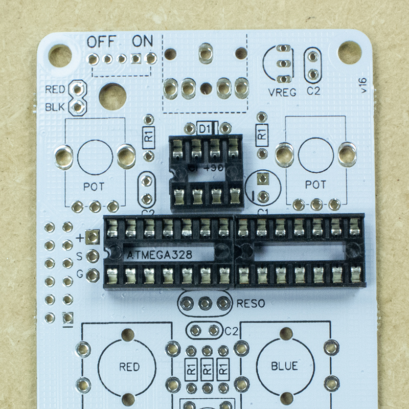
1. Sockets
The first thing to install is the DIP sockets. They will hold the chip and keep them from getting damaged by the soldering iron’s heat.
They don’t have a direction but it’s standard to put them in with the little notch on the left.
Use a small flat head screwdriver to fold the legs towards each other.

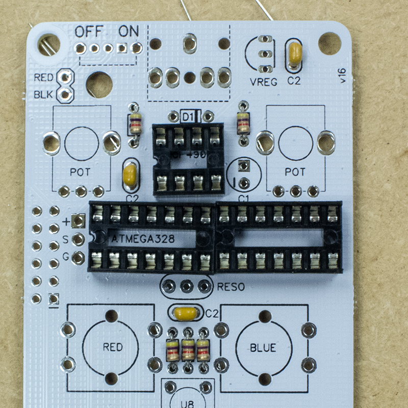
2. Resistors
There are five place places on the board marked R1 where 4.7K resistors should be installed.
They are a little hard to read but they stripes on them are yellow, purple, red, and gold. They are the only resistor in your kit with a purple stripe. Resistors are not polar so you can install them in either direction.
Fold the legs as shown. The next steps will be easier if the legs overlap as little as possible on the bottom.


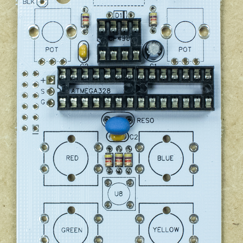
3. Capacitors
Next are the three small .1uF “ceramic” capacitors taht go in the spaces marked C2. They are not polar and can be installed in either direction. Fold the legs as before.
A few kits made it out the door with only one .1uF cap but the device will work just the same. Install it in the space in the middle of the PCB under RESO and leave the others empty. I’ll still send you the extra caps so if you did only get the one email me at drbleep@bleeplabs.com
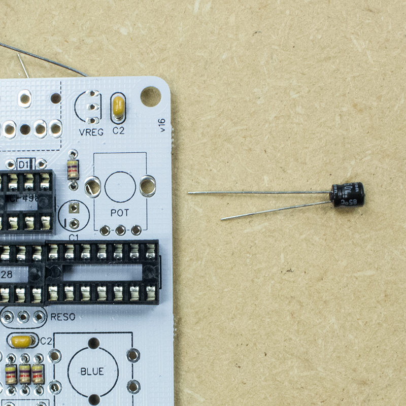
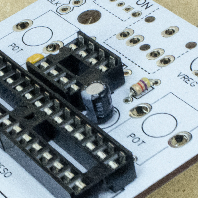
The 2.2uF capacitor is a small cylinder with one leg sorter than the other.
It is polar, with the short leg needing to go in the circular hole.
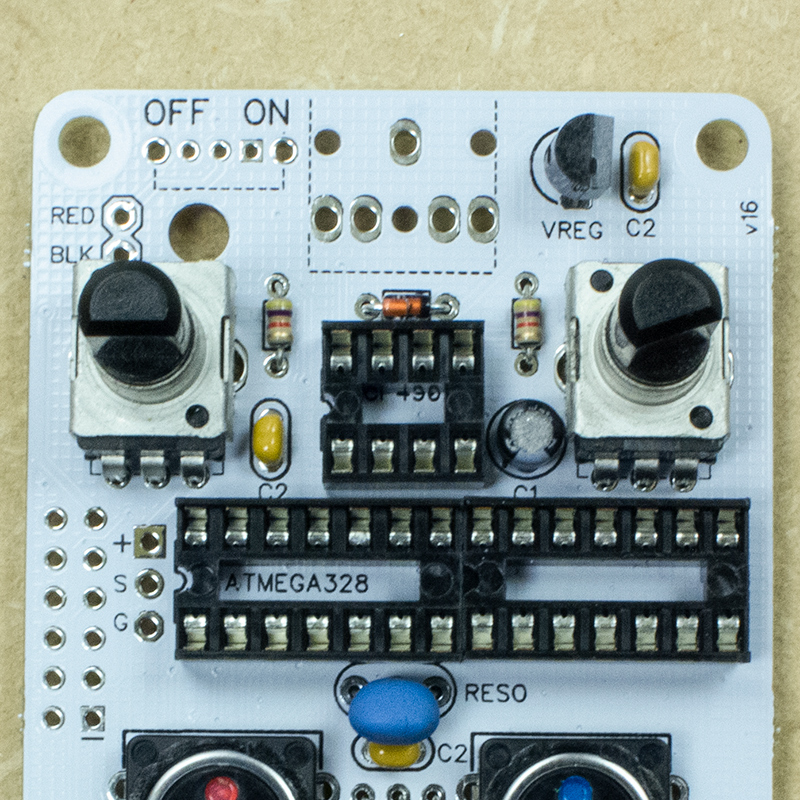
4. Resonator
The resonator can be installed in either direction. It’s legs are pretty short so just bend them over, no clipping needed.
5. VREG
The 78l05 voltage regulator needs to go in with the curved part on the left as the outline on the circuit board shows.
Do not try to push it all the way down. You should still be able to see the legs. Bend the legs like before.

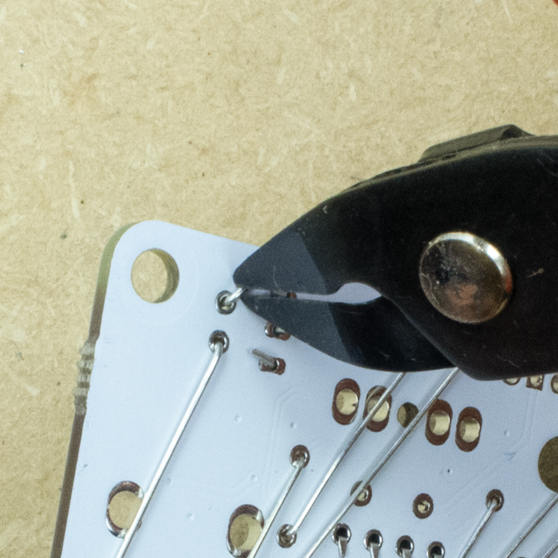
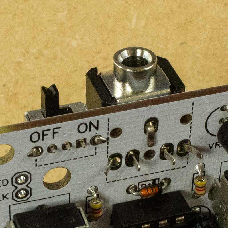
6. Snipping
With all of these parts installed we can snip off all the leads on the bottom.

Using your flush cutters snip the legs so there’s enough to hold the part in but no so much it will touch something else. Wear safety glasses as the leads can go flying. Make sure you’re not going to hit anyone else with them either!
I like to cut the leads off in a paper grocery bag or deep box so they don’t go everywhere.
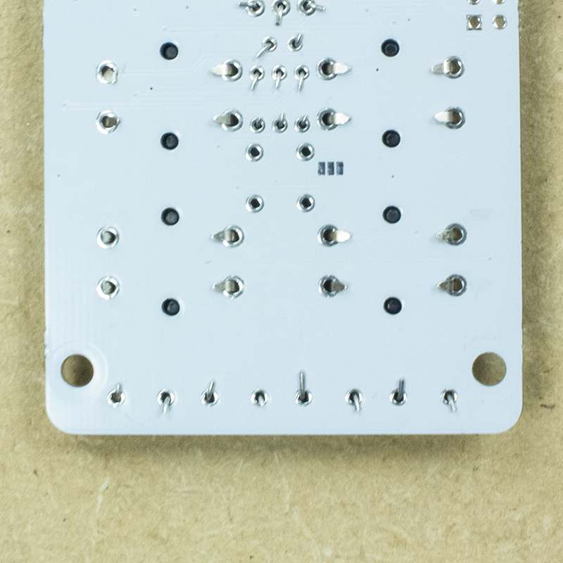
The pink arrow shows a leg that is a little short. This resistor might fall out so mare sure it looks good before soldering.
The teal arrow shows a leg that is a little long and might be getting to close to another pad. It would be best to more it out of the way or snip it a little more.

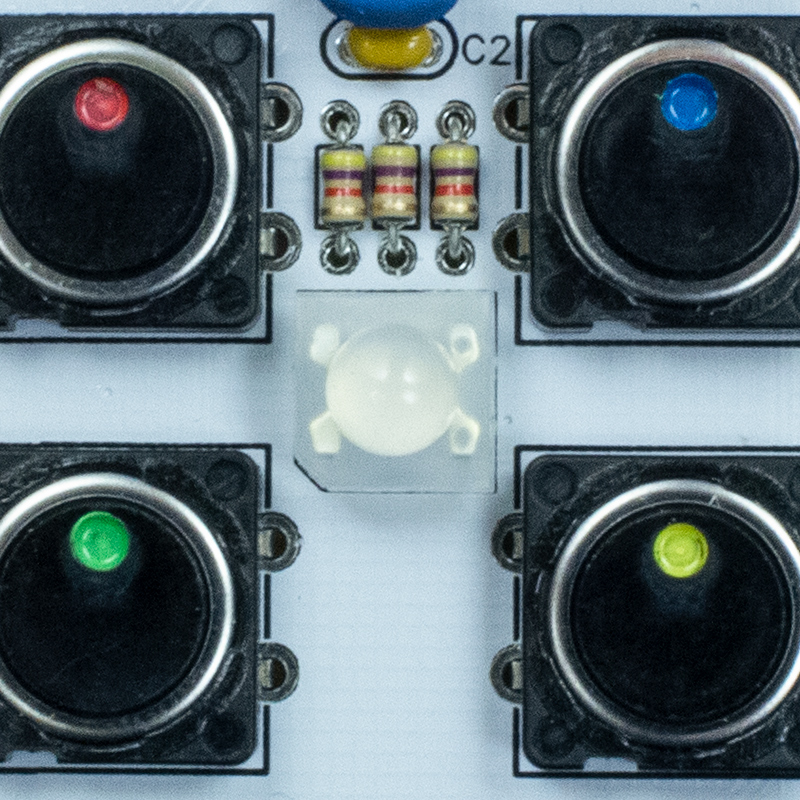
7. Buttons
The buttons don’t have a direction. install them as shown.
Bend and snip the legs of the small ones as before. For the large ones just bend their legs towards the center.

8. LED
This LED has one angled corner. make sure its on the lower left as indicated on the board. Bend it’s legs towards the middle.
9. Pots and diode
The pots snap in but you might need to bend the large tabs on them to get them to fit.
One installed you might have to bend their legs towards the center but if they feel secure it’s fine.
The diode needs to have the black band on the right. Make sure of this before you snip it’s legs.
10. Soldering
Now that all the top side parts are in we can solder. First make sure you’ve read and understand the safety guide. For real!
If you solder iron tip isn’t in good condition (it’s ashy, blackened, pock-marked, or just isn’t melting solder) you will cause more harm than good. Get a new tip or iron from this guide.
The basic idea is that we are heating the part and the hole and pushing the solder in where the part, hole and soldering iron tip meet.
Heat the part for a couple of seconds.
Add a small amount of solder.
Keep heating after you’ve removed the solder until it has flowed and forms an even little mountain.
If you need more solder just repeat the process.
Here’s a great in depth video on soldering
For larger holed like those on the sides of the pot its ok if you can still see the hole. For everything else you don’t want it to be visible. You can see here I just add enough solder to get it to hold one corner of the pots and ! don’t heat it for too long.
Remember when you’re soldering everything metal touching the tip will get hot pretty quick. That means all the metal on the other side of the pot.
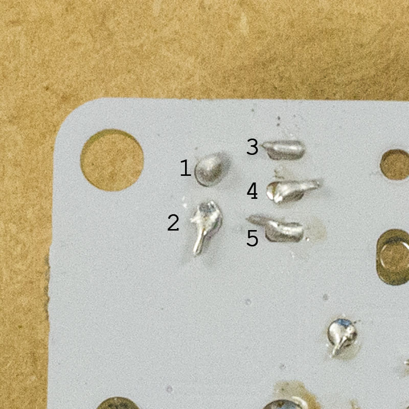
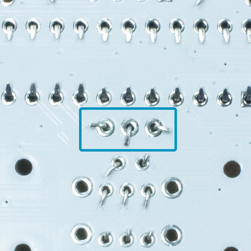
A few issues:
#1 – Too much solder. Not the worst but might not be making a great connection. Heat it up to see if it flows though to the other side and form a nice peak.
#2 – It’s hard to tell bu this one needs to be re heated too. Its a bit messy which can be a sign that it’s not making good contact with the hole. Just heat it up again and add a tiny bit of solder to get it flowing.
#4 – needs more solder. You should not be able to see any part of the pad or hole.
#3 & #5 and the one hanging out in the lower right looks good.
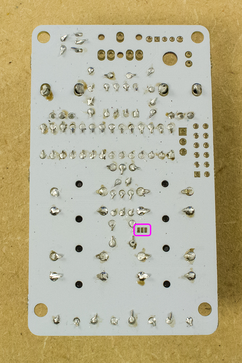
Don’t worry if your soldering doesn’t look beautiful, though. There will also probably be some brown or black marks left by the flux depending on your type of solder.
If they look very charred, turn down the heat on your iron. All of this below looks fine.
Ignore the pads in the pink square. The were there in case the LED had to be a different type.
11. Bottom parts.
The power switch and output jack are installed from the bottom. Bend their legs as shown to make sure they are in securely then solder them.Your output jack might have 5 or 3 pins and could look a little different. They all work just the same.
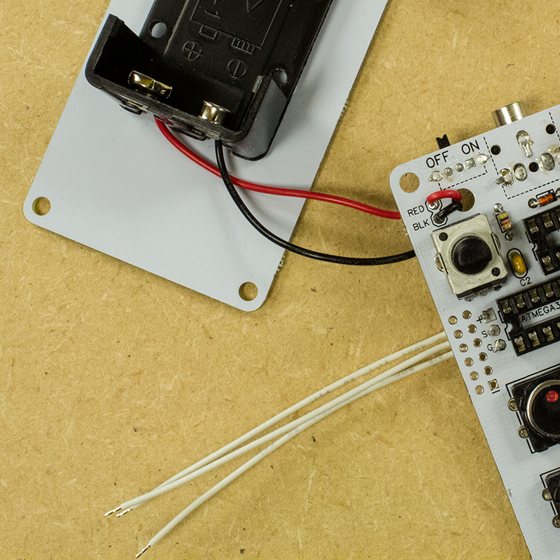
12. Wires
Three wires are soldered on the top side of the board to the pads left of the “ATMEGA328”. They might be white or light blue.
The 9V battery wires go up through the hole then into the board, being soldered on the bottom.
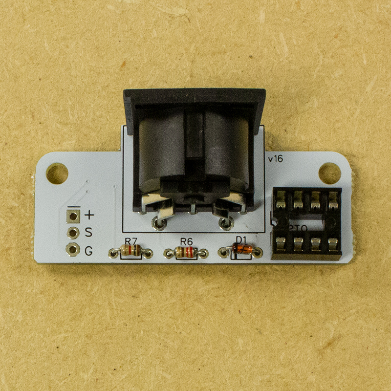
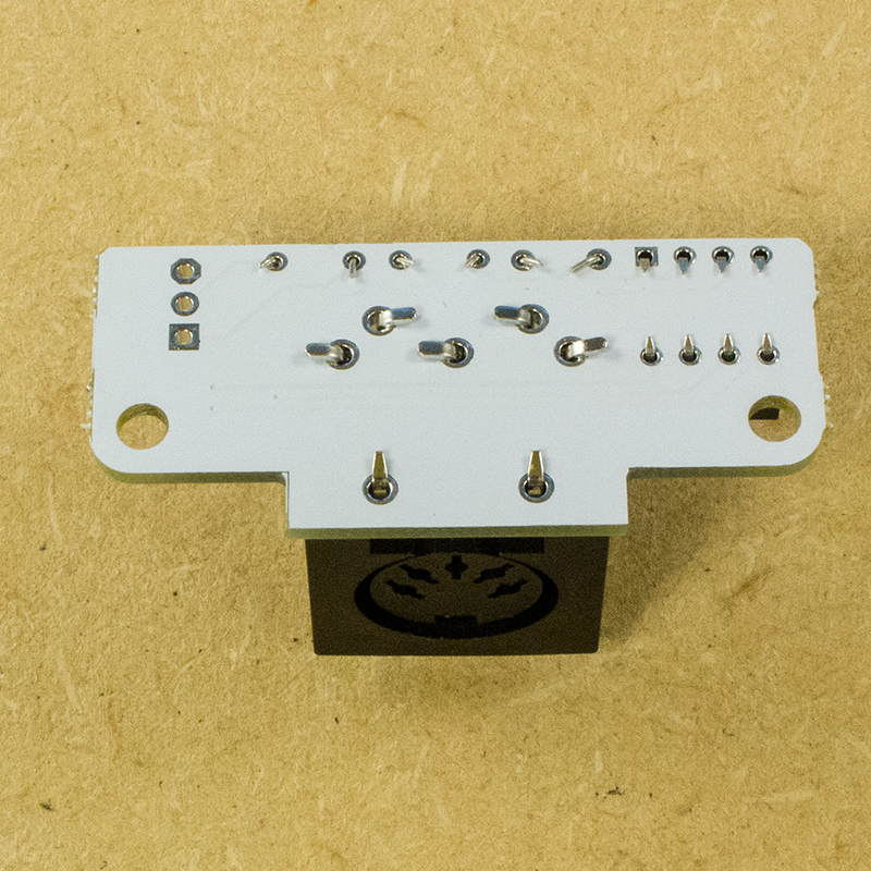
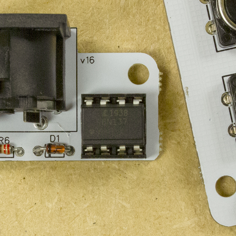
13. MIDI
The MIDI board has a 1k Ohm resistor (brown black red gold) in R7 and a 220 ohm (Red red brown gold) in R6.
A diode with the line on the right goes in D1. The dip socket goes in same as before.
For the large jack carefully bend all of its legs down. You might need a decently large screwdriver to do this.
Solder these parts then solder the wires from the main board to their corresponding pads on the MIDI board.
14. Testing
Inset the chips as shown.
The large chip and the one marked MCP4901 are for the main board. Install them with the little notches on the left.
On the MIDI board the 6n137 chip has a embossed edge that should be on the bottom
It will help later on if you twist the wires together as shown.

Before putting in a battery make sure
– The chips are in the correct direction
– All the wires are going to the correct places
– No pads are touching other pads.
If it’s looking good you’re ready to turn it on and test that all the functions are working.
If it’s not working:
– See what pads might not be soldered all the way as discussed here.
– Try a new battery
– Make sure the battery is fully snapped in to the connector
– Make sure the wires are well soldered and going to the correct pads.
– Check that all the chips are in the correct direction and are pressed all the way down.
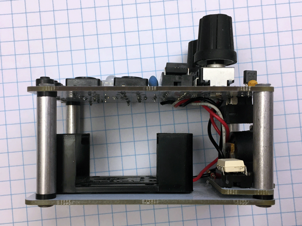
15. Hardware
Now we can screw it all together.
There are two different sized standoffs. First we’ll use the shorter ones.
If your kit had round aluminum legs you will need to install the washers as shown here.
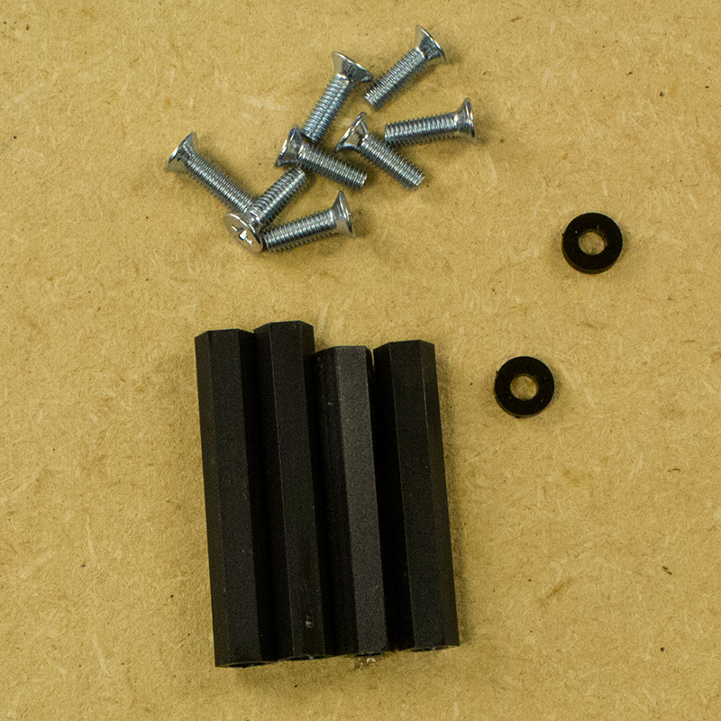
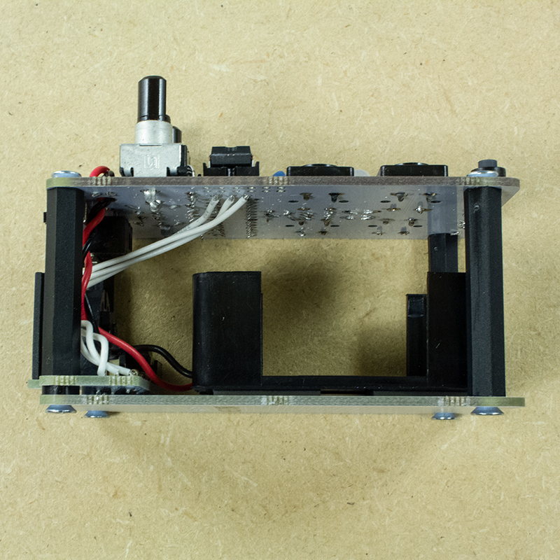
Put screw in the bottom on the side with the battery wires as shown. Put washers on the other sides.
Then put on the MIDI board, then the short standoffs. You don’t really need a screwdriver, just tighten the standoffs with your fingers.


The other side is just screws and the longer standoffs.

The top goes on with just screws. Don’t over tighten them with the screw driver.
Make sure the wires aren’t in the way of the battery holder
16 Finishing
If you have some isopropyl alcohol, clean off the bottom screws and stick the four feet on them. Cleaning with anything will help them stick better, just make very sure the screws are dry before sticking the feet on.
All that’s left is to put the knobs on the pots. There’s only one way they an go on and friction will hold them in place.
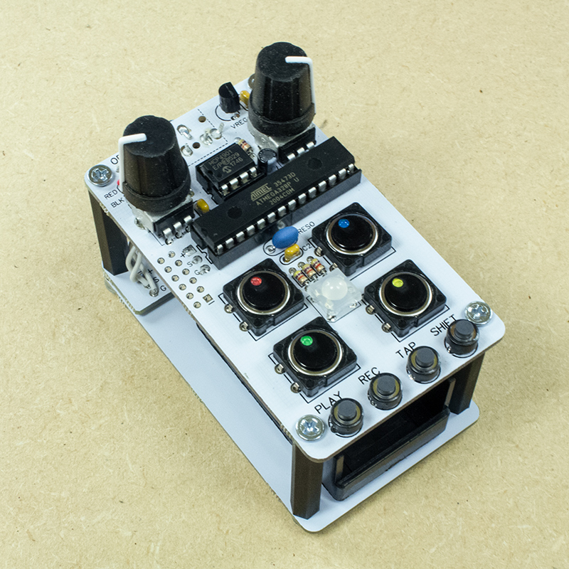
Now go make some noisy beats!
User guide and hacking info
Tag Bleep Labs if you post about your new drum friend on instagram or twitter.
Email drbleep@bleeplabs.com if you have any questions at all.
Thanks!