The Breadboard
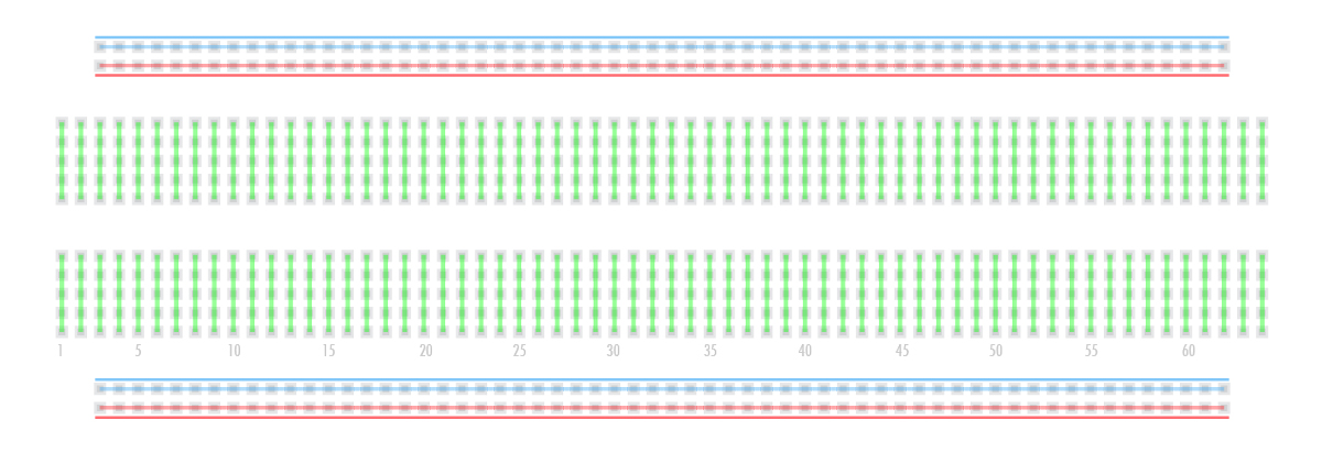
Breadboards allow us to easily construct and change electronic circuits. The holes on a breadboard are connected as show.
The vertical strips on either side of the central gap are connected in groups of five.
The horizontal red and blue “bus” lines are connected all the way across the board.
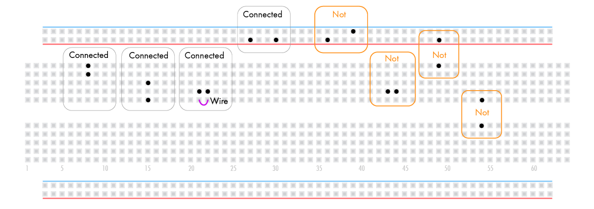
This means that if you put a wire or components in each of the dots show in the left examples they will be connected but not if you have them installed as show in the right examples.
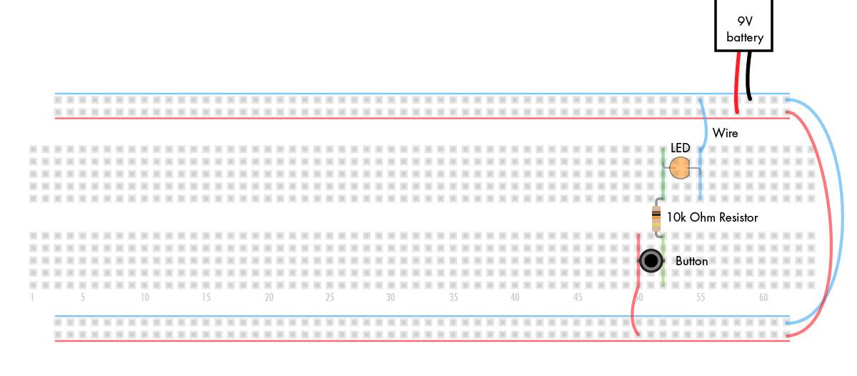
Let’s start by making a very simple circuit.
LEDs are polar, meaning they need to be installed in the circuit in the correct direction.
Notice the notch on the right side of the LED in this diagram. It corresponds to the notch on the LED itself. This cathode lead of the LED is also shorted than the anode one.
When you press the button the LED will turn on. If not:
– Are all the components in the proper rows and columns as shown? The circuit doesn’t have to be built exactly as show but if, for example, the bottom red wire isn’t in the same column as the pin of the button, the circuit won’t work.
– Is the LED polarity correct?
– Is the battery polarity correct?
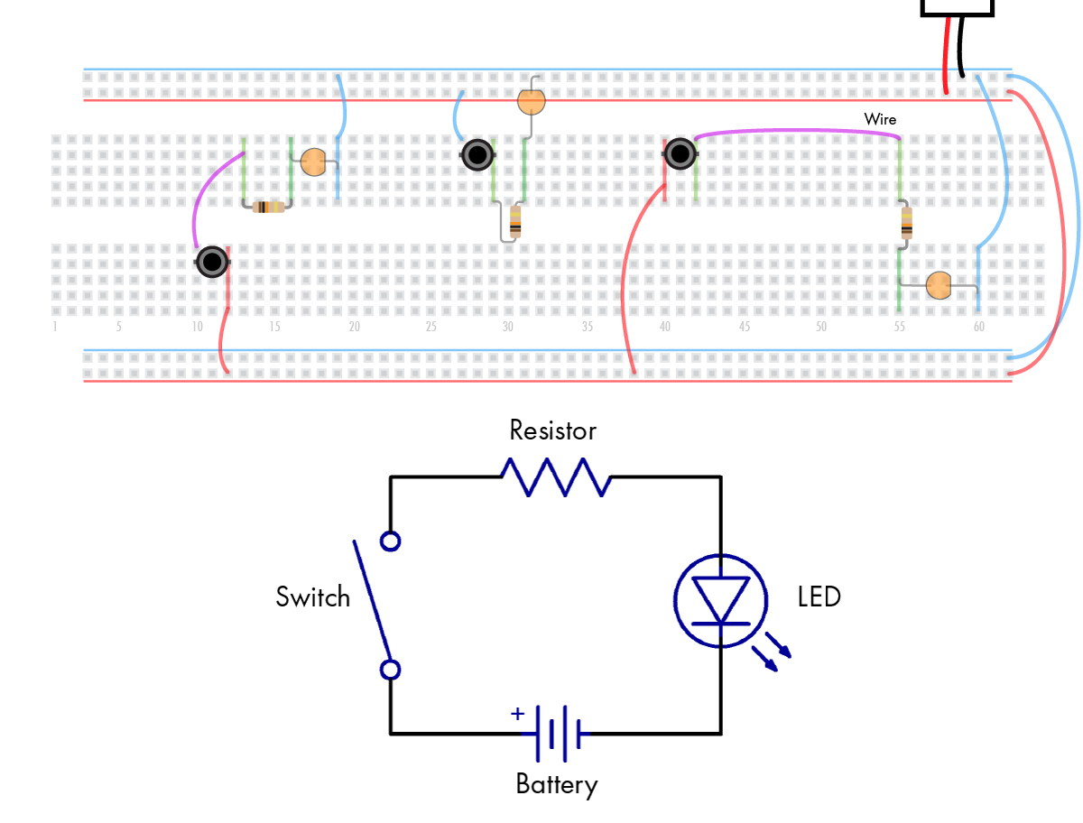
The same circuit can be built in many ways on the breadboard. For example all of these are the same as this circuit you just made.
The 40106
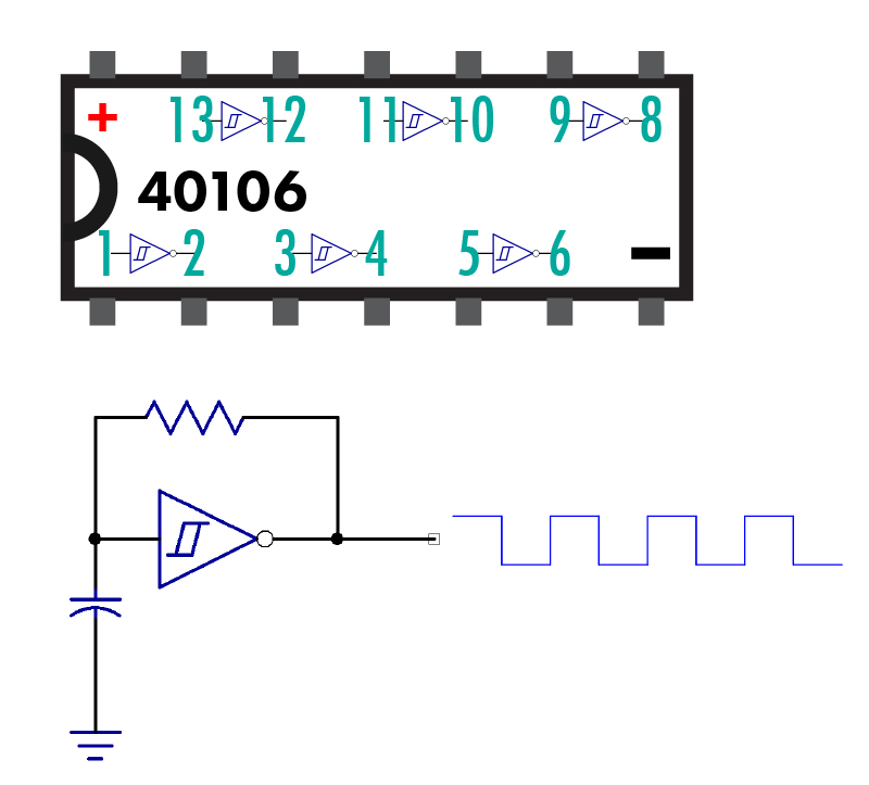
The 40106 (aka 74HC14) is a hex schmitt trigger. All that means for us is that there are six separate devices in it that can all be turned
into an oscillator with just a resistor and capacitor.
Install the components starting with the potentiometer and IC, then add the other components and then wires. Always use the smallest wire that will comfortably connect the two points.
We don’t need to install things in exactly the same places as show n in the diagrams but you need to be close as we’ll be filling up the whole breadboard and won’t have a lot of wiggle room.
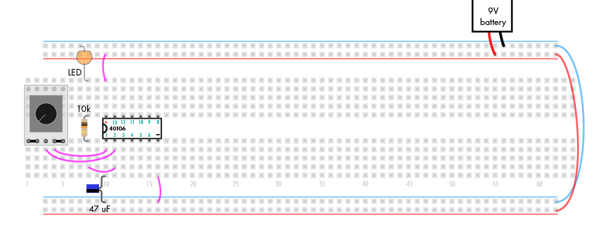
Starting on the left we have a potentiometer. The left two and right two pins are connected, as indicated by the little black lines. The pins on the back side are not connected to anything.
The 40106 IC should go in with the notch on the left side. The notch on yours should be painted blue.
The 47uF capacitor is polar, just like the LED. The short leg is the negative one and there will be some kind of stripe on the side with a “-” mark. The colors might vary from this illustration.
The 10k resistor is not polar. It can go in either way.
Before plugging the battery in :
– Make sure the chip is right side up with the notch on the left
– The battery wires are connected to the right places
– All the wires going to the chip are correct
Now you have an oscillator blinking the LED!
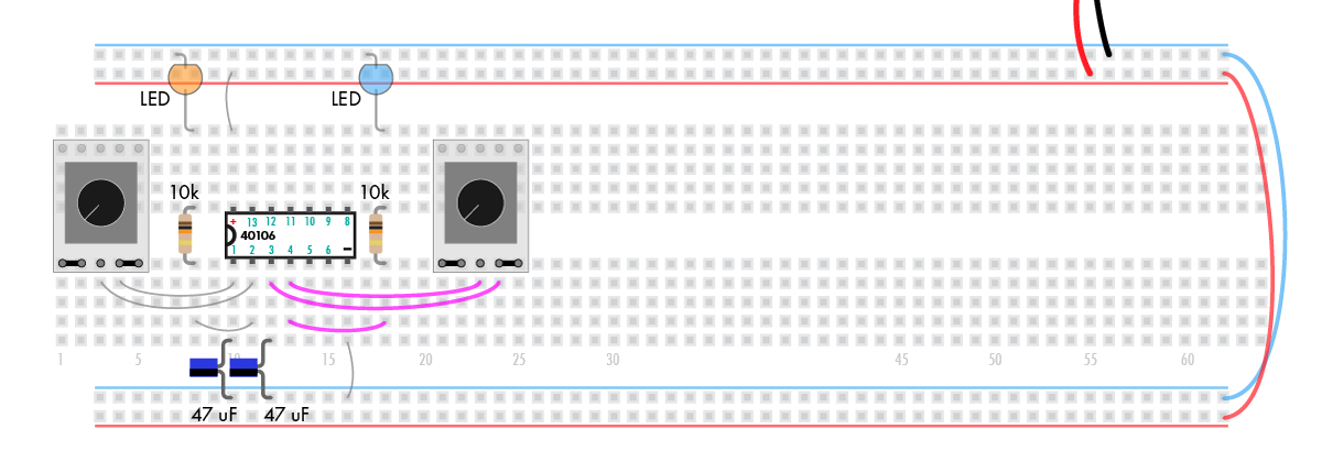
Lets add a second, independent oscillator.
Pink wires are new, grey ones are from the previous steps.
Making sound
What if we want to hear these oscillators?
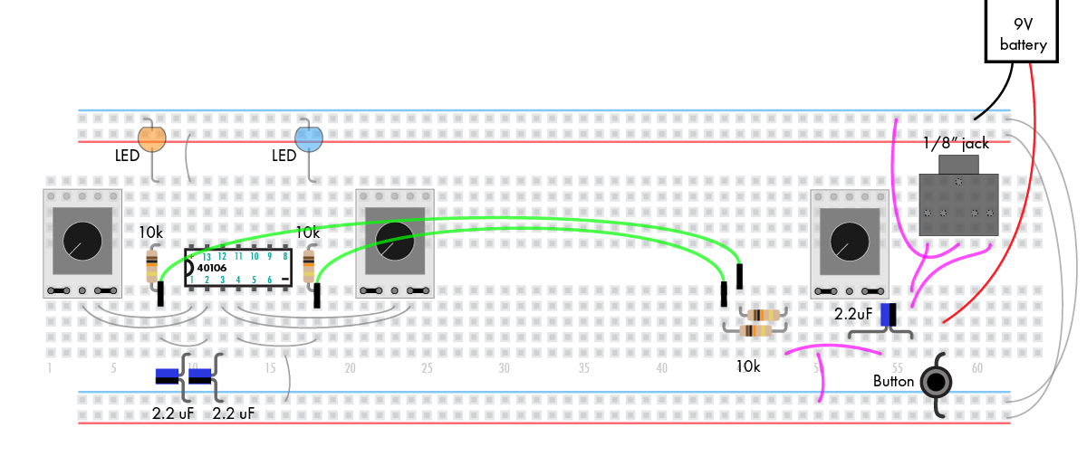
The first step will be to make them much faster. We can do this by replacing 47uF capacitors with 2.2uF ones. Just as changing the resistance of the circuit changed the speed, changing the cap can alter it too.
On the right side of the circuit we’ve added a “mixer” composed of three 10k capacitors and a volume knob.
This goes to another 2.2uF cap then a 1/8″ jack which connects to your headphones. Make sure all the pins of the jack are going into the breadboard as indicated.
The green wires with black ends are these types of wires in your kit. You can peel them apart from each other if they are still connected in a ribbon.
A button has been added and the 9V positive wire has been moved to it so the button activates two independent oscillators.
If you’re not hearing anything :
– As before, is a component off by a row somewhere?
– Is the volume turned up?
– Are the pins of the jack in correctly?
– Is the battery connected to the button as shown?
If you are using an amp or mixer or interface to listen to your device disconnect the wire going to the right of the jack.
This wire lets you hear the devices through both headphones but will cause problems with a mono plug.
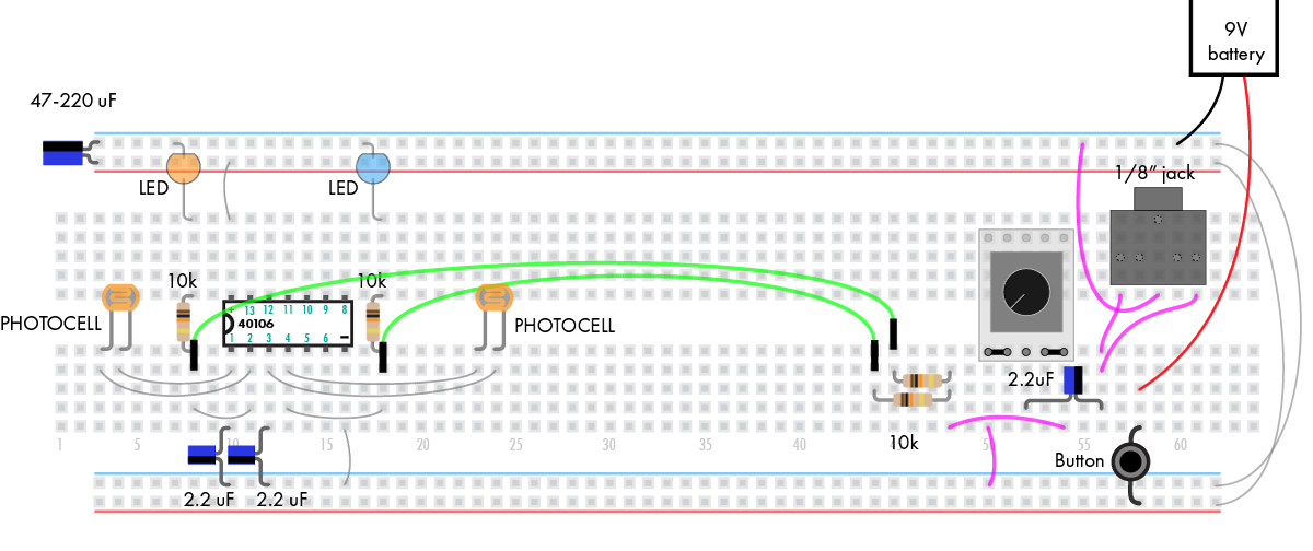
Let’s change a few things to make the circuit a little more interesting.
Replace the potentiometers with photocells. Now the oscillators will change pitch based on how much light is hitting them. try covering them up or pointing a flashlight at them.
By adding a 47uf Or 220uF capacitor across the positive and ground rows we can add a decay to the button. Once you push the button the cap fills up with current and stays that way untill you release it. That current then goes through the circuit and is enough to power it for a little bit of time. As the voltage is dropping quickly the volume decreases and the oscillators change pitch in an interesting way.
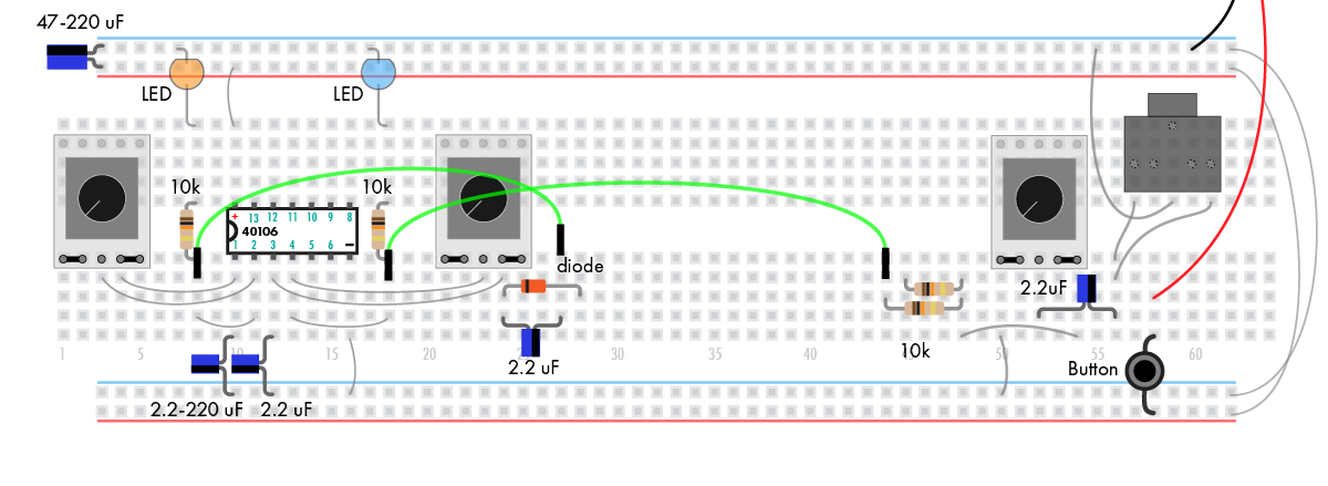
Now lets use one oscillator to modulate another one.
Potentiometers are used in this example just to make things a little more clear. You can experiment with the photocells ones you’re sure it’s working correctly.
Add a 2.2uF capacitor and diode as shown. The diode must go in with the line on the left.
When you connect the output of the left oscillator to the right side of the new cap you’ll be changing the right oscillators frequency in a kind of siren effect. When the left osc is low, the new cap is changing the rate of the right osc so the pitch is lowered.
When you connect the left osc to the right side of the diode the right osx will be turned off when the left osc is low.
Try changing the capacitor of the left osc for different rates of modulation.
The 4040
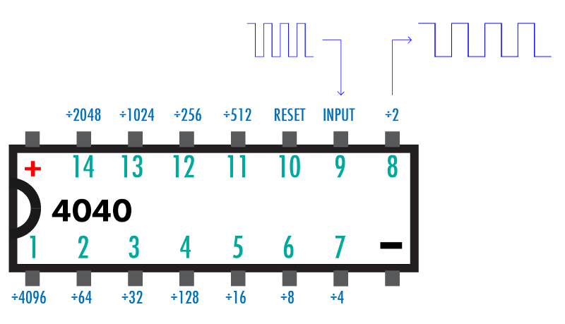
This chip is a 12-stage binary ripple counter. That means and incoming square wave’s frequency is divided in half 12 times. Here’s an animation of an 8 stage divider.
If your input is 440 Hz then pin 8 would output 220Hz, pin 7 outputs 110Hz and pin 6 outputs 55Hz. All at the same time.
This lets you build a complex waveform by combining outputs. It also just so happens that it sounds very musical as dividing a frequency by two gives you an octave down.
In this example we are hearing one oscillator as well as the the same oscillator one octave down (÷ 2) and are using the ÷ 256 output to modulate that same oscillator.

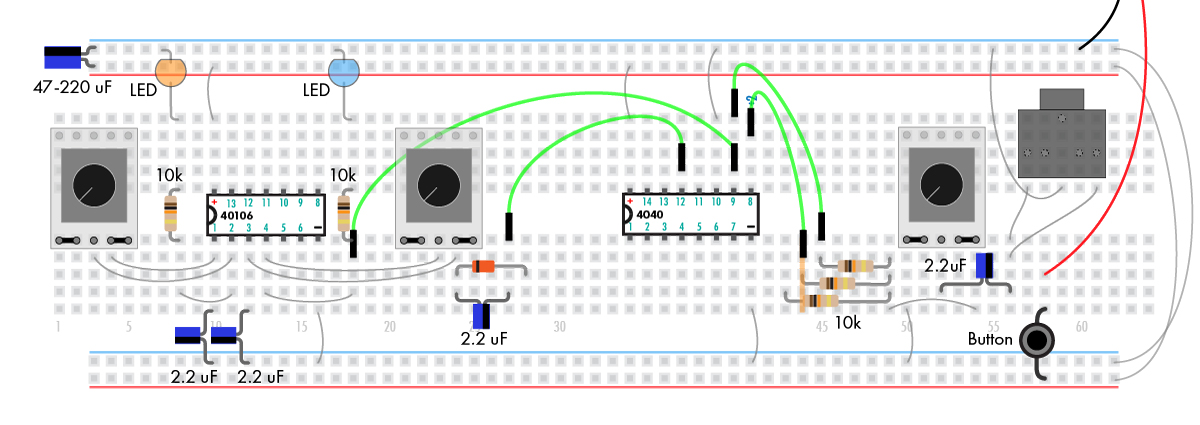
Now you can get to experimenting!
Here a second diode and 2.2uF cap pair have been added to the left oscillator.
The green columns are outputs, pink ones are inputs and the orange ones are three separate output channels.
Try:
– Using the slower outputs (256 and bigger) in the different inputs. They can also be attached to LEDs of their own through 10k Resistors.
– Using photocells instead of caps.
– If you want the device on all the time just install the red battery wire in the red row.
– Output 3 of the faster outputs at the same time
– Change the oscillator and power capacitors.
– Attaching the divided outputs back into the inputs of the oscillator that is driving it gives more structured sounds while putting them into the other oscillator and listening to both makes for more random noises.
Remember to remove the purple wire attached to the jack if you’re using a mono plug.
Feel free to email or facebook message me with any questions.
Want to make more noise? Here are some resources to help you continue your DIY synthesis journey.