Nebulophone main page
Before you begin, check out the soldering guide for more info about tools and videos on soldering properly.
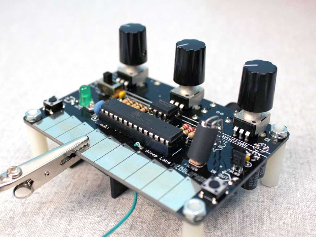
Please note there are several different versions of the Nebulophone circuit board. They are all roughly the same and any major differences have been noted here in the instructions.All versions are functionally the same.
Pictured here is the most recent version, 09.
______________________________________________________________________________________________________________________
Top side
Start by installing all the parts that go on the top of the circuit board, or “PCB”.
Refer to the parts list for help differentiating all the little electronic doo-dads. Note that parts might look slightly different than the ones pictured here.

DIPs
These are sockets that protect the chips from direct soldering. The chips, or “ICs” will be installed after all the soldering is done.
Insert the DIPs into the outlined spaces. One 8-pin DIP in the small space marked “IC2” and two 14-pins in the large “IC1” space. Orientation of the DIPs does not matter. Bend the pins toward each other using your flat head screwdriver once they are in..
______________________________________________________________________________________________________________________
78L05
This is a voltage regulator that powers the Atmega328 chip.
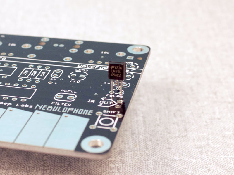
Bend the leads out slightly so they fit into the PCB. Don’t push the 78L05 all the way down, it should stand a little above the board.
Make sure that it’s in the correct direction and clip off the excess leads. Leads can shoot off with some force so be sure to wear your safety glasses. The best place to cut is just on the outside of the pad, leaving enough lead for the part to hang on but not too much so that it could touch another pad.
Older board might have the three pads in a row instead. Simply bed the other legs out to insert the part.
______________________________________________________________________________________________________________________
Resistors
Bend the leads of the resistor down so that the part resembles a U and insert the leads into the PCB. Then flatten the leads away from the resistor and clip the excess off just as you did before.
Put a 220 ohm resistor in the space marked R1.

______________________________________________________________________________________________________________________
Capacitors
The small, yellowish caps are not polar, meaning you can put them in either direction. Put the four .1uF caps in their holes then fold and cut the leads just like the resistors.
Don’t put the large caps in yet, they will go in from the bottom.
Resonator
The resonator goes in just the same. Direction doesn’t matter on it either.
It might be blue and smaller than the one shown.

______________________________________________________________________________________________________________________
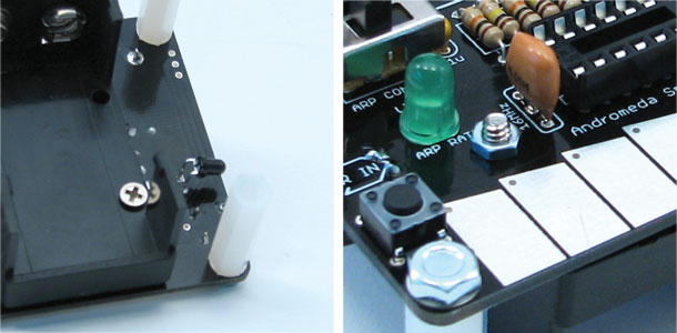
Switches and Pots
Insert the switches and pots as shown. They all snap into place and do not require their leads to be clipped before soldering. Direction on the buttons and switches does not matter.

______________________________________________________________________________________________________________________
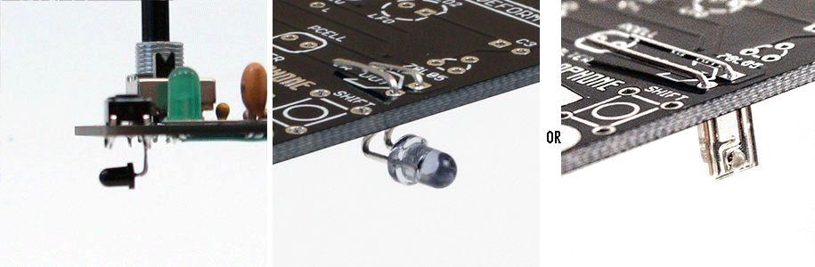
Photocell and LEDs
Note that the placement of these parts might be flipped on your board.
Insert the photocell all the way into the board. Direction does not matter.
Direction does matter on the LEDs. For the green LED1, put the shorter lead into the square pad. The flat side of the LED should line up with the diagram on the PCB.
LED 2 goes in with the short lead in the square hole as well but stand up off the board as shown. This allows it to bend around and illuminate the photocell. You can also use the small rubber tube included to block out light to the photocell so only the LED is effecting it.

______________________________________________________________________________________________________________________
Soldering
With all the top side components in it’s time to solder. First check if everything is in the correct places.

Before you solder make sure that your soldering iron is in good shape. If your tip is torn up, you might destroy the pads. The tip should be clean, shiny and not have any craters in it. If you’re unsure if your iron is the right type or if you have any other questions about soldering, see soldering guide for more info.
We soldering, remember to heat the part then push the solder into the joint. Don’t try and “paint” the solder on.
1 – Heat the part for 2 seconds.
2 – Push in just enough solder to cover the joint
3 – Remove solder but continue heating joint for 2 seconds.
First, solder the switches and pots. Make sure the part is perpendicular to the board before you solder it.
Next just work in lines from top to bottom so you don’t miss any pads or connect any leads together.
______________________________________________________________________________________________________________________
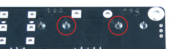
After everything is soldered, use your cutters to trim the two pads circled above in red. Be careful though as they might go shooting off!
This is done so that the battery compartment fits flush to the PCB.
______________________________________________________________________________________________________________________
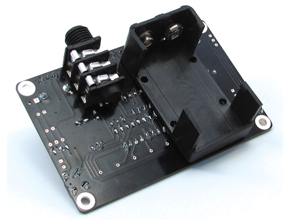
Bottom Side
Now you can move on to the bottom components.
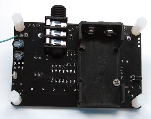
If your battery compartment has pins it will install like this:
Insert the tiny 4-40 screw and tighten it’s nut on. Don’t put it on super tight, just enough to keep the battery holder from moving.
If your part has wires it will look like this, with the red wire in the round pad and the black in the square.
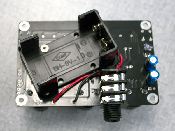
Install the screw and nut as seen above.
The 1/4″ jack is the same on either. Insert it from the bottom, making sure that it is flush with the PCB before soldering.
______________________________________________________________________________________________________________________
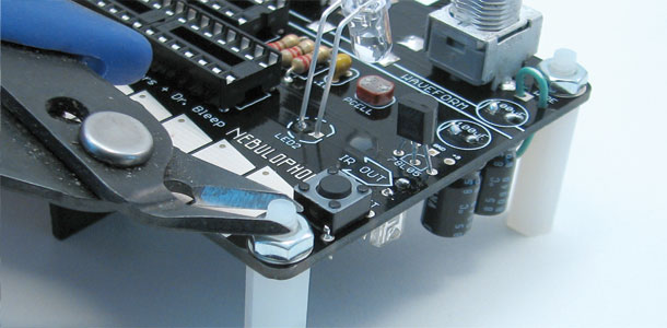
The IR components are next. These allow the Nebulophone to communicate with other Andromeda Space Rocker devices and the HSS3i.
The black detector goes in the IR IN pads with the short leg in the square pad. The bluish emitter goes in the IR OUT the same way, or if you received a rectangular emitter, make sure that the side with the bump is facing outward.
______________________________________________________________________________________________________________________
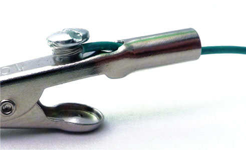
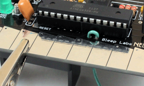
Next in is the stylus wire. First, strip off about 1/2” from an 8” piece of wire. Then insert the wire into the alligator clip as shown and tighten the screw.
______________________________________________________________________________________________________________________
Take the other end of the stylus wire and push it up from the bottom of the board then back down in to the square “WIRE” pad.
Once it’s soldered in you can install the large capacitors. make sure to put them in with the sides marked with a “-” stripe going into the square holes. Note that the included capacitor might be 100uF of 220uf but they work just the same.
______________________________________________________________________________________________________________________
Install the white plastic standoffs by inserting them from the bottom and screwing the 6-32 nut on top. Clip the excess off of the front legs but be careful of flying plastic bits!
______________________________________________________________________________________________________________________
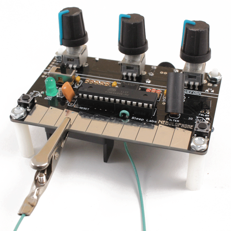
Now you can push on the knobs and put the chips in their sockets. Make sure that the text on the chips is right side up before putting a battery in
Take the small black tube and place it over the LED and photocell.
Carefully insert the chips into the DIPs. Make sure the are in the correct direction. The text should be right side up and the half circle or dot should be on the left.
______________________________________________________________________________________________________________________
Test
Once you’ve checked that everything is installed and in the correct place, it’s time to test it out!
The Nebulophone turns on when you plug a mono 1/4” cable into it. A stereo cable will not turn it on. LED1 should immediately start blinking and once LED2 is on, it’s ready to start synthesizing the finest in digital tonalities!
______________________________________________________________________________________________________________________
Troubleshooting
– Are the chips in the correct direction?
– Is the battery dead?
– Do all the solder point look like they should? It’s not enough for there to just be some solder on them. Large blobs of solder might not be conducting properly. YOu should not be able to see the pad.
– Are you using a mono 1/4″ plug? A stereo one will not turn it on.
– Are any points touching?
– Is the wiring correct?
If it doesn’t come on and you’ve checked everything a couple times, the best advice is to come back to it later. Seriously! I cannot count the number of times I have spent hours infuriated by a project, only to look at it the next day and find the problem immediately. If you still have problem, feel free to contact us at drbleep@bleeplabs.com
______________________________________________________________________________________________________________________
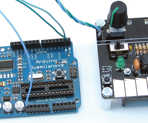
It’s easy to hook the Nebulophone up to an Arduino programmer!
Simply connect the RX TX and Rst pad on the Neb to an Arduino programmer. Remove any chip that’s in the Arduino board and power up the Nebulophone.
Check the latest code and modification info here.
______________________________________________________________________________________________________________________