Build instructions | User guide | Code | Board layout
Full size
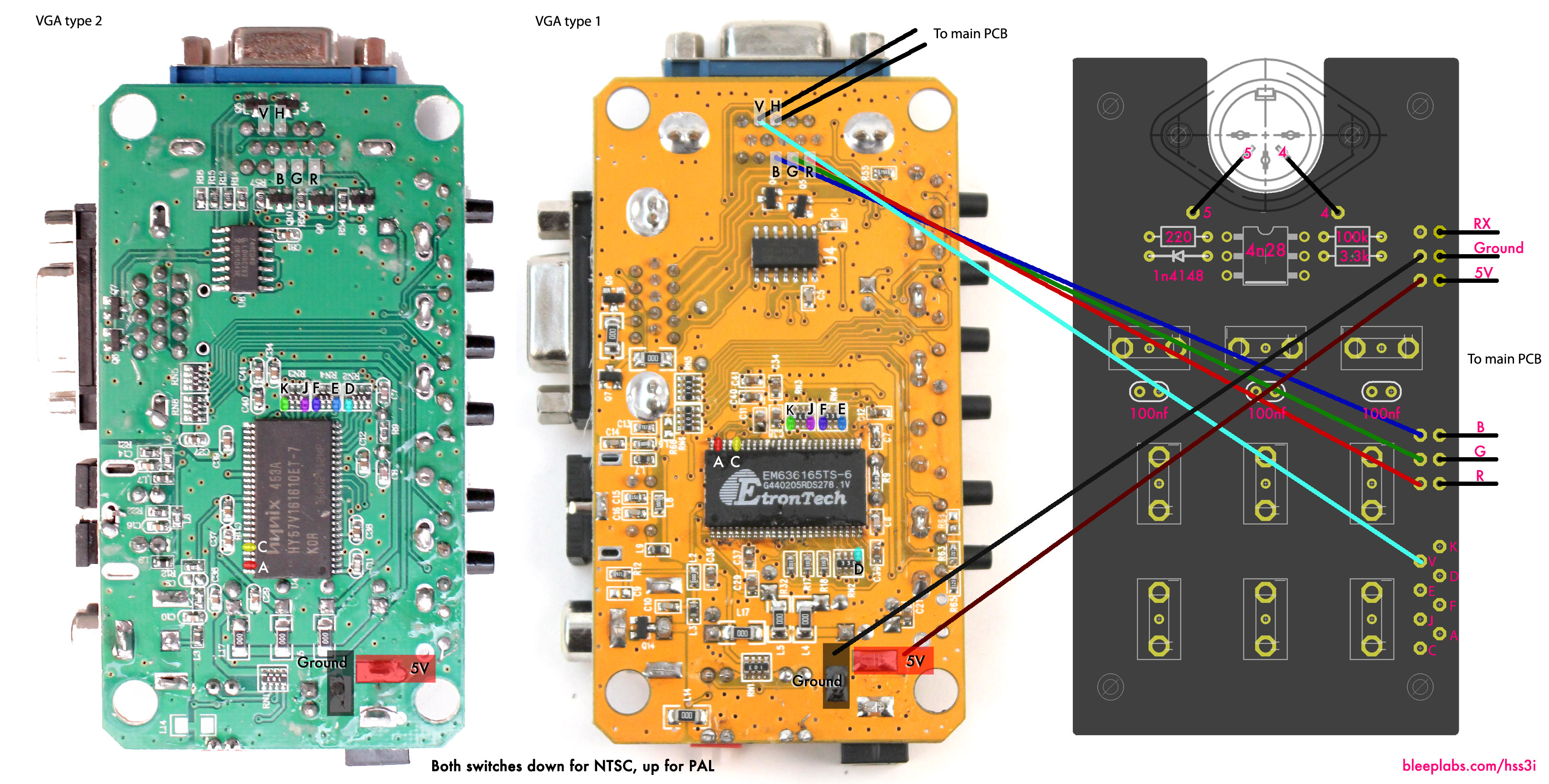
The VGA converter device allows the HSS3i to output mind-baffling video signals. It has RCA, s-video, and VGA outputs, but note that we only can ensure the RCA’s functionality. The digital outs may not work on all devices. To hook it up to the HSS3i, first remove the four screws and take off the case.
Solder the wires to the VGA pins as shown at the top of the video board. If you are going to also build the MIDI + Bend PCB, DON’T solder the R, G and B wires yet. Make sure that no pins are touching one another.
Use the black wire included with your kit to hook up RGBHV and power. The thin white wires are for the bends.
These wires go to their corresponding places on the HSS3i.
Modification note : The R G & B wires control those color and can be interchanged or connected. A patch bay would be a way great to get even more video madness.
Connect a black wire to the video board’s ground and a red to 5V. Connect these to their corresponding places on the HSS3i
Once all the wires are in the correct places, power up the HSS3i and hook up a monitor. NEVER plug a power adapter into the VGA converter, only the HSS3i. You can use the menu buttons on the side to adjust the picture. If there’s no color, turn the two DIP switches down. (PAL TVs should have them both up.)
_______________________________________________________________________________________
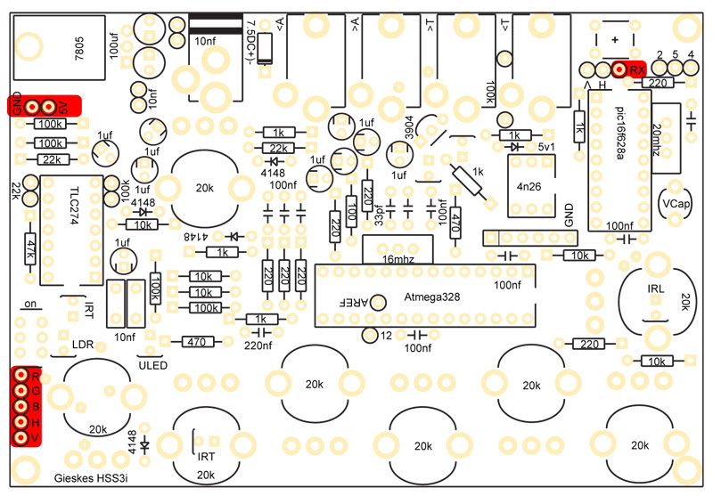
The MIDI board allows the HSS3i to accept MIDI as well as alter the video.
Install the components as shown, making sure the line on the diode is to the left. Use screws and nuts to hold the MIDI jack in place.
When installing the 4n26 chip, make sure it’s oriented so that the indented circle is in the upper left (when the MIDI board is oriented with the jack at the top).
Connect the three wires to the MIDI board. Connect the 5V and ground wires from the MIDI board to the video converter board, then to the HSS3i.
Use wires to connect one row of RGB pads to the R, G, and B pads on the HSS3i. The other row, shown in the picture above, needs to be connected to the video converter.
The three 100nf caps can be colored red, green and blue in that order if you wish.
_______________________________________________________________________________________
Bending!
Keep in mind that this is done at the user’s risk. The video converter device is very fragile, and soldering tiny SMD parts can be tricky and might damage the device. Also the bent video signal will only show up on the RCA out. The VGA and s-video signal will be clean.
Take the thin precut wires and connect them to the video converter device as shown in the pictures at the top of this page. It’s easiest to add solder to just the wire then heat the wire and pad together. After they are attached to the video device, solder them to MIDI board as shown.
Modification note: There are more pads that act as bend points (and inputs!). A patch bay would be great for this too. Be careful; we killed several devices during bend testing!

Now it’s time to screw it all together.


On the video & midi side the screw goes through the bottom first. Then:
1 – Small standoff
2 – Washer
3 – Video device
4 – Washer
5 – Long standoff
6 – Midi board
7 – Nut (large)
Congratulations!
Have fun with your new HSS3i. Watch bleeplabs.com or gieskes.nl for code updates.