The Hard Soft Synth 3i by Gieskes.
User guide | Parts list | Code | Board layout | Video, MIDI, bend, and mounting instructions
This is an intermediate level kit. This means that while it is no more difficult to solder than any of our other kits, the HSS3i is much larger and requires more attention to detail. Refer to the Soldering 101 if you need help getting started.
It is very important that you know how to solder safely before you start. This includes working in a well-ventilated area and wearing safety glasses. Children should never solder without adult supervision and should never handle anything that might contain lead.
Here is the PCB layout to refer to as you go:

____________________________________________________________________________________________________
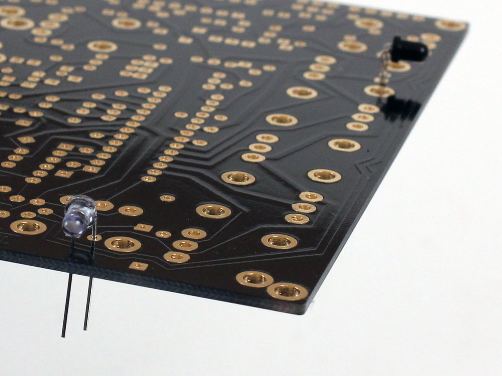
The IR emitter and detector go in first.
Flip the board over and install the clear blue tinted emitter in the space marked IRL on the top. The short lead will go in the ground pad. The black receiver goes in the space marked IRT also with the short led in the round pad.
____________________________________________________________________________________________________
DIPs. Orientation of the DIPs does not matter. Bend the pins toward each other using your flat head screwdriver once they are in.


____________________________________________________________________________________________________
Resistors. Direction does not matter. Note how there are both horizontally and vertically mounted ones.

____________________________________________________________________________________________________
Ceramic capacitors, usually small and yellow, have no polarity and can go in either direction. Electrolytic caps, cylindrical and tall, have a polarity and must go in the correct direction. The short lead on the side with the the stripe goes in the square pad.

____________________________________________________________________________________________________
Transistors need to go in the direction indicated on the board. Just line up the shape of the body with the outline on the PCB.
The 7805 in the top corner should mount flat to the board with the holes lining up.

____________________________________________________________________________________________________
Diodes also need to go in the correct direction. The line on the diode corresponds with the line on the diagram.

LEDs should go in with their short lead in the circular hole. The flat side should line up with the line on the board.

The LED in the lower left corner doesn’t mount all the way to the PCB. It should stand off as shown so that its light strikes the photocell as shown. The photocell can go in either direction.

____________________________________________________________________________________________________
And the rest. The variable capacitor and crystals can go in either direction. Note that the crystal mounts in the two outer holes of its space. The middle hole stays empty.

Huge size.
* Note that there should be a DIP here, not the 4n26
With all of these components in, it’s time to solder the top components. Refer to the soldering section if necessary.
Once all the small components are done, you can install the rest of the parts. Potentiometers and jacks go in as shown. The button and switch can go in in either direction. You can solder these parts in as you go so they won’t fall out.
____________________________________________________________________________________________________
Now it’s time to test! Before you power it up, make sure that all of the points are fully soldered. You shouldn’t be able to see any of the pads or holes. Also, no two solder points should be touching each other. Use your iron to clear any bridges between pads.
Install the chips so that the half circle at one edge lines up with the marking on the PCB as shown. The 4n26 does not have a half circle, but it does have a small indented circle on the same side where a half circle would be. Make sure that they are in the correct direction before you power the HSS3i on.

If everything looks good, plug it in to a 7.5 Volt DC adapter with a positive tip. Anything about 300mA should be fine. Be sure the polarity is correct as you can very quickly burn out the diode, 7805 and your finger if it’s backwards!
The symbol on the adapter should similar to this :![]()
______________________________________________________________________________________________________________________
Troubleshooting
– Are all of the chips in the correct direction?
– Is the DC adapter correct?
– Do all the solder point look like they should? It’s not enough for there to just be some solder on them. Large blobs of solder might not be conducting properly. YOu should not be able to see the pad.
– Are any points touching?
– Is the wiring correct?
If it doesn’t come on and you’ve checked everything a couple times, the best advice is to come back to it later. Seriously! I cannot count the number of times I have spent hours infuriated by a project, only to look at it the next day and find the problem immediately. If you still have problem, feel free to contact us at drbleep@bleeplabs.com
____________________________________________________________________________________________________
Continue on to:
Video, MIDI, bend, and mounting instructions.