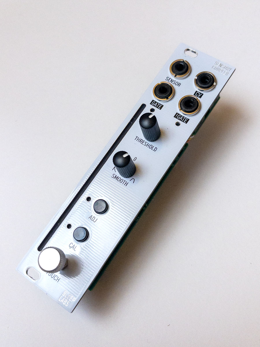
The Sensory Coupler allows you to convert touch, proximity, light, magnetic fields, motion, and more into CV and gate.
The media on this page is only for retailers and is not the final content that will be used to promote the device.
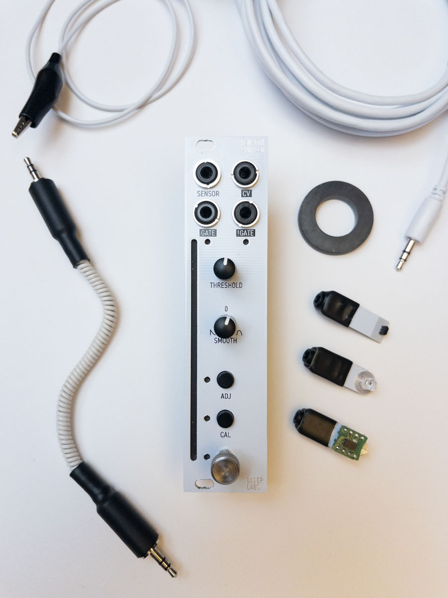
The module includes:
– Phototransistor / light sensor
– Hall effect / magnetic sensor
– Accelerometer / motion sensor
– Gooseneck 1/8″ TRS cable. Flexible and stays in place.
– 2M 1/8″ TRS cable. Has a higher gauge than a regular 1/8″ modular cable, allowing for sensors to be connected at a distance without introducing noise.
– 50mm long alligator clip wire for touch sensor
– Donut magnet
Other sensors and devices like expression pedals can be easily added with the DIY info I’ll be releasing.
6 hp, 32mm deep
+12V 100mA
5V 0mA
-12V 12 mA
The device will have CE and WEEE logos on the back PCB.
Pricing
This device will only be sold through retailers.
Retail price is $250 for the USA. Other countries can include shipping and import costs of course.
Wholesale price is 175 each for 4+ units. Free demo unit for 10+
Device ships in a printed tuck top box and includes a small plastic container for the sensors
A 50% down payment paid by Sept 1st will be needed to get production going.
Timeline
I would want the unit in all stores at the same time before sales begin.
Delivery can happen by November 1st if orders are made in the next 2 weeks. I do not foresee any supply chain issues and have most of the critical things already.
Demo units can be sent out in 4-5 weeks.
Contact me with any other questions! drbleep@bleeplabs.com
The Future(?)
I plan on putting some other modules out next year as well.
Once some chips become available I’d like to put out a learning platform I’ve been working on for a while that would have lots of fun built in modes but also go along with free videos where I teach how to program you own synth in Arduino. really it’s an asynchronous version of my dadageek classes with better hardware.
A simple 4hp dual VU with LEDs similar to the on on this device should be easy to produce and might be popular.
A “built-to-bend” delay module where you make glitch sounds by directly patching to a memory chip.
Device usage:
SENSOR JACK –
TRS sensor input. Only works with included or DIY sensors but really it’s just: Tip-3.3V, ring CV in, Sleeve-ground. CV in is limited to 0-3.3V. Attaching this to any other input or output will not cause any issues on either device.
CV – 0-10V CV out based on sensor.
The GATE output is high when the sensor level is less that the threshold level, indicated by a white dot on the LED strip. !GATE will always option the opposite of the GATE signal so it’s high when the sensor level is above the threshold level. These two jacks allow you to have a falling edge in both directions of crossing the threshold level.
THRESHOLD KNOB – Sets the level of the gate threshold. Indicated by a white dot on the LED strip
SMOOTH KNOB – When set to 12:00 there is no smoothing between the sensor and the final output. In this mode the LEDs indicating the sensor lever are green to yellow.
On the left the sensor reading controls an envelope follower. The output will rise instantly to a new higher reading of the sensor but fall gradually based on the knob position. LEDs are purple to magenta.
On the right the signal is averaged. When turned up a little this removes noise for a florescent lightbulb for instance. As you increases the amount the output slowly rises and falls.
ADJ BUTTON – Sets the output mode when pressed. Four levels are shown on the LED strip when ADJ is active. Top is 0-10V output, next is 0-5V. The third one down is 0-5V but the sensor mapping is inverted. Instead of a bright light or touch with more pressure increasing the level is lowers it. The last level is 0-10V output that’s inverted like the previous level.
Hold ADJ and turn threshold to change the threshold from a level to a zone. now GATE will be high only when the sensor level is inside the illuminated area.
Hold ADJ and turn smooth to set the brightness of the LEDs.
CAL BUTTON – Calibrate the sensor input so it covers the entire output range. Press the button and the CAL light will start to blink. While it’s blinking the device is looking at the incoming high an low levels of the signal. On touch for example, you’d move you hands far away from the sensor then pressed on it firmly. This would set the 0V output to not being pressed and the 10V output to firmly pressed. is the sensor picked up a level higher or lower than what was set, it will just output the programed high and low.
The TOUCH SENSOR is active then nothing is in the SENSOR jack. A while light turn on next to it to confirm if it is active.
The LED STRIP shows the current sensor level in a color set by the smooth mode, as well as the threshold level or zone in white.