This project can be completed by those who are new to soldering, but it is very important that you know how to solder safely before you start. This includes working in a well-ventilated area and wearing safety glasses.
Check out bleeplabs.com/kits for more info about tools and videos on soldering properly.
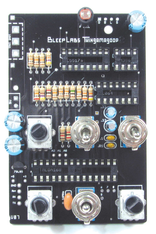
Begin by installing all the parts that go on the top of the circuit board, or “PCB”. Refer to the parts list for help differentiating all the little electronic doo-dads. Note that location of some part on your circuit board might differ from those pictured here. Simply place parts in the spots indicated on your board.
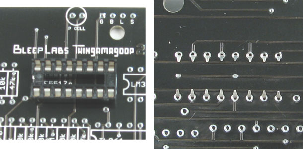
DIPs
These are sockets that protect the chips from direct soldering. The chips, or “ICs” will be installed after all the soldering is done.
Insert the DIPs into the outlined spaces. One 8-pin DIP in the small space and two 14-pins in the large ATMEGA168 space. Orientation of the DIPs does not matter. Bend the pins toward each other using your flat head screwdriver once they are in..
______________________________________________________________________________________________________________________
78L05
This is a voltage regulator that powers the AVR chip.
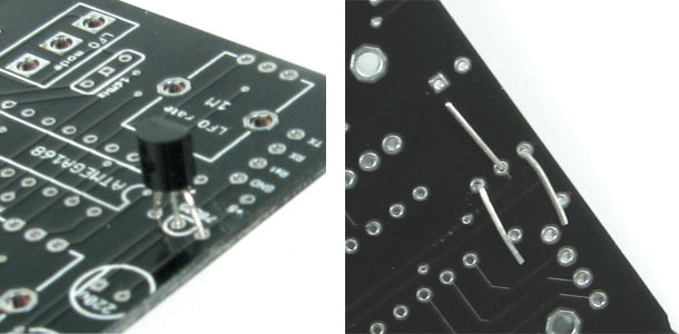
Bend the leads out slightly so they fir into the PCB. Don’t push the 78L05 all the way down, it should stand a little above the board.
Make sure that it’s in the correct direction and clip off the excess leads. Leads can shoot off with some force so be sure to wear your safety glasses. The best place to cut is just on the outside of the pad, leaving enough lead for the part to hang on but not too much so that it could touch another pad.
______________________________________________________________________________________________________________________
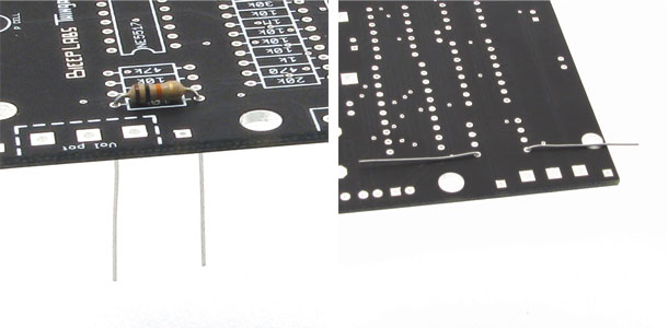
Resistors
Starting with the first value on the left (10k), install all of the resistors for that value and move on to the next value until all 7 resistors are installed. Put a 220 resistor in the space marked “R1”. Direction of the resistors does not matter.
Bend the leads of the resistor down so that the part resembles a U and insert the leads into the PCB. Then flatten the leads away from the resistor and clip the excess off just as you did before.
______________________________________________________________________________________________________________________
Capacitors
The small, yellowish caps are not polar, meaning you can put them in either direction. The larger caps are polar and must go in with their short leads in the square pads.
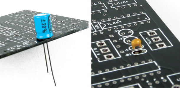
If you have a larger, cylindrical cap with 10uF marked on the side, this goes into the top most space between the pitch and A/D switches.

Resonator
The resonator goes in just the same. Direction doesn’t matter on.
______________________________________________________________________________________________________________________
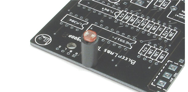
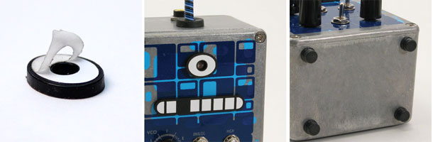
Photocell
Insert the photocell into the standoff then into the board. Make sure to fold the leads down tightly so the standoff doesn’t wiggle.
______________________________________________________________________________________________________________________
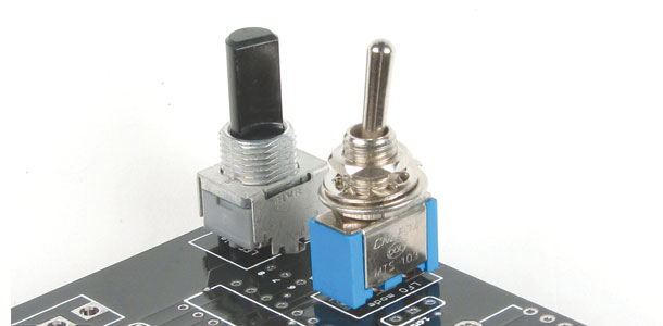
Switches and Pots
There are two types of switches. One with three positions and two switches with only two positions. The switch with three positions goes in the MOD space.
All three of the potentiometers currently included with kits are 10k or 20k (marked B1 03 or B2 03 on the underside). Place one in each potentiometer space, regardless of how the PCB is marked.
If your kit is older and one of the pots is 1M (marked 05 on the bottom) and two are 10k (marked B1 03), place the 1M pot in space for LFO rate and the 10k pots in the other two spaces.
Now that all the PCB components are in and their leads are clipped, it’s time to solder. We’ll add the switch potentiometer and do the wiring after everything on top is soldered.
______________________________________________________________________________________________________________________
With all the top side components in. it’s time to solder. First check if everything is in the correct places.
Before you solder make sure that your soldering iron is in good shape. If your tip is torn up, you might destroy the pads. The tip should be clean, shiny and not have any craters in it. If you’re unsure if your iron is the right type or if you have any other questions about soldering, see bleeplabs.com/thingamagoop2 for more info.
We soldering, remember to heat the part then push the solder into the joint. Don’t try and “paint” the solder on.
1 – Heat the part for 2 seconds.
2 – Push in just enough solder to cover the joint
3 – Remove solder but continue heating joint for 2 seconds.
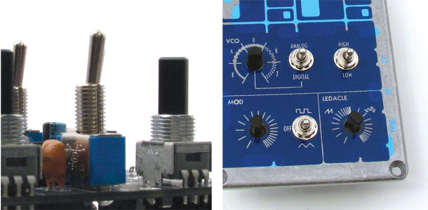
First, solder the switches and pots. Make sure the part is perpendicular to the board before you solder it.
Next just work in lines from top to bottom so you don’t miss any pads or connect any leads together.
______________________________________________________________________________________________________________________
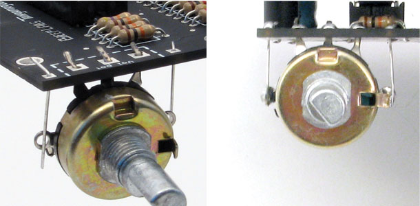
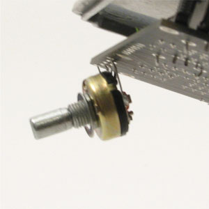
Switch Pot
The switch pot goes in on the top let corner. Push it in and solder the middle three leads. Then use small lengths of wire or leftover resistor leads to connect the lugs on the side to the outside pads. Fold the small tab on the side out.
______________________________________________________________________________________________________________________
Battery Connector
Thread the leads of the 9V battery clip through the hole on the left side.
Solder the black wire into the square 9V pad and the red wire into the circular pad. It’s best to solder and clip the extra leads as you go.
______________________________________________________________________________________________________________________
Internal LEDs
If you are putting together a Thingamagoop 2 with a clear front follow along here.
For Thingamagoop 2Xs with colored fronts scroll down to the next section.
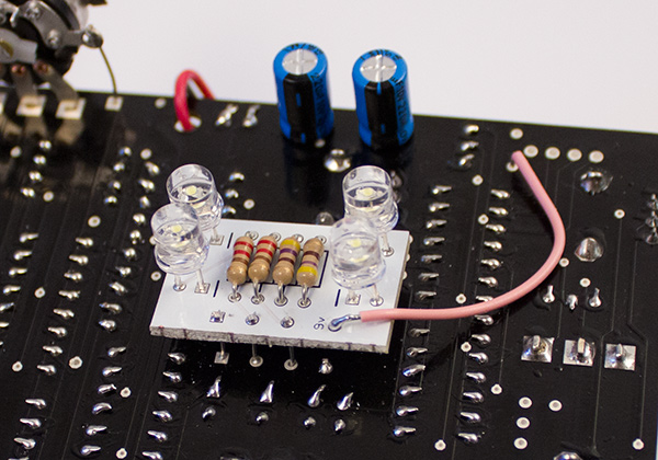
Thingamagoop 2xs with clear fronts:
Note that the board might be white.
Install the six resistors just as before. Use 100 Ohm resistors (brown black brown) in the spaces marked 82.
The LEDs go in as shown. The longest lead goes into the square pad.
Attach four leads clipped from the resistors to the four pads on the edge of the board. These will connect to the main Thingamagoop 2 PCB.
Mount the two boards together, leaving about 1/4″ of space between them. The lead with square pad will go into the square pad on the the main PCB.
Make sure there is plenty of space between the two boards before soldering them all the way.
______________________________________________________________________________________________________________________
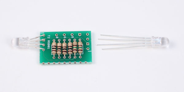
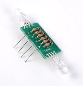
Thingamagoop 2xs with colored fronts:
Install the resistors and LEDs as shown. R1 is 220 Ohms (red red brown) and R2 is 470 Ohms (yellow purple brown).
Make sure that the short leg of the LED goes in the square hole with the dash next to it.
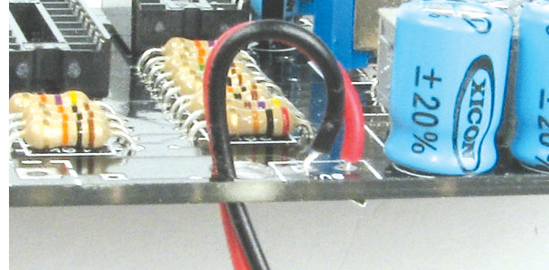
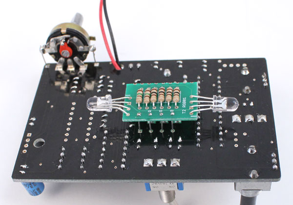
The top three pads go into the top three holes in the middle of the Thingamagoop. The last pad is connected by a wire to the 9v pads shown here.
Make sure there is plenty of space between the two boards before soldering them all the way.
______________________________________________________________________________________________________________________
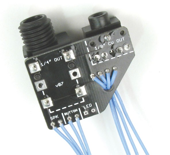
Output PCB.
Start by cutting and stripping the lengths of wires (your wire color might be different than shown). You should create four wires that are about six inches long and four wires that are three inches long.
Solder the four longer wires to the “G B L S” pads on the right and thread them through the hole as shown.
The shorter wires go in the “SPK” and “Button” pads. Nothing goes in the “LED” holes quite yet.
The 1/4” and 1/8” jacks go in from the bottom and are soldered on top.
______________________________________________________________________________________________________________________
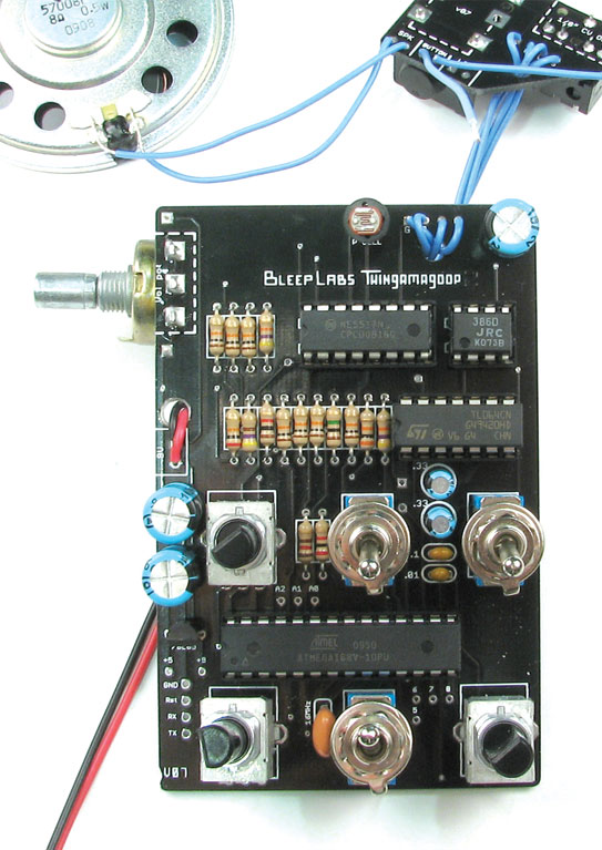
Wiring
Next, solder the other ends of the “SPK” wires to the speaker’s pads. Polarity doesn’t matter.
Now you can solder the long “G B L S” wires to their corresponding places on the main PCB as shown. Don’t wire the button or LEDacle up yet.
______________________________________________________________________________________________________________________
Now it’s time to test! Insert the chips into their corresponding DIPs with their text right-side up.
Before you put in a 9v battery, there are a few things to test:
– Wiring: Make sure each of the “G B L S” wires is going to the correct place.
– Chips : Are they in the correct way?
– Capacitors: Electrolytic caps on the right side have their black marks on the left, and the two 220uFs on the left side have their black marks on the right.
– Solder side: Make sure that all of the points are fully soldered. You shouldn’t be able to see any of the pads or holes. Also, no two solder points should be touching each other. Use your iron to clear any bridges between pads.
Once everything looks good, turn the top middle switch up, snap in a battery and turn the switch pot on. You should be instantly delighted by bleepish noise!
If it doesn’t come on and you’ve checked everything a couple of times, the best advice is to come back to it later. Seriously. I cannot count the number of times I have spent hours infuriated by a project, only to look at it the next day and find the problem immediately. If it’s still not working, please email us at drbleep@bleeplabs.com
______________________________________________________________________________________________________________________
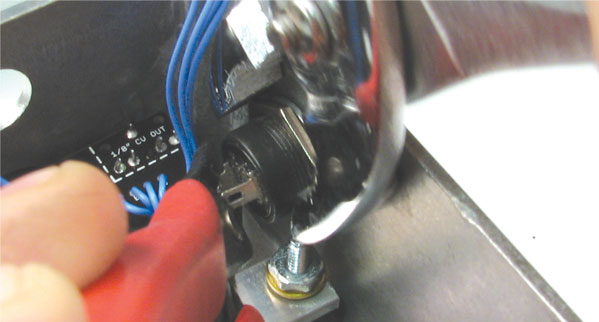
Enclosure
Put the 1/4″ jack through the hole as shown and tighten the black plastic nut on the other side. There is no washer for the jack. (Yours will have wires soldered too it of course.)
Place the screen over the slots.

______________________________________________________________________________________________________________________
Make sure no pieces of metal have become stuck to either side of the speaker and place it on the screen.
Put the screws through the back and screw them through the speakers holes until it is firmly held down.
Then tighten nuts on with your pliers.

______________________________________________________________________________________________________________________
Put the button in the large hole on the side and use pliers to tigthen it up. Hold onto both lugs with one set of pliers and tighten with the other.
Then solder the wires from the “Button” pad to the button’s lugs. Be careful to not heat the button’s lugs for too long, as the plastic will melt.
______________________________________________________________________________________________________________________
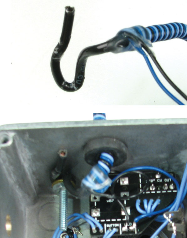
The LEDacle goes in next. Put the grommet in the other hole on the top and push the LEDacle through it.
Bend the LEDacle as shown and loop it over the screw on the left. Put the star washer then flat waster over it and tigten it down with a nut.
Solder the ledacle wires to the board, making sure to put the black wire in the square hole.
______________________________________________________________________________________________________________________
Push the 9v snap through the hole in the battery box. Snap a battery a battery in and test to make sure everything is working.
Now for the front plate. Start by removing all the nuts and washers from the switches. Tun all the switches on and slide the top plate on. Place the star washers on the switches then tighten a washer on. You won’t need the rest of the hardware.
The old T2 front is shown here but the clear one mount’s the same. Just take care not to leave fingerprints on the inside.
______________________________________________________________________________________________________________________
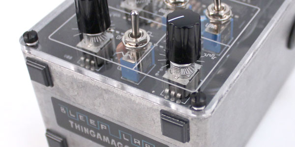
Bend the volume pot inward slightly and put the plate on the enclosure.
______________________________________________________________________________________________________________________
If everything looks and sounds good you can screw the top on. Use the black plastic screws on the front panel. Then place a nut on the switch pot and tighten it up. No washer is needed.
Now that all the insides are done you can put the knobs on. Place the knobs on the potentiometer shafts with the screw facing the flat sides of the shafts. Tighten the screws up, making sure to leave about 1-2 mm of clearance between the enclosure and the knob.
______________________________________________________________________________________________________________________
The last step is to put the faces and feet on. Peel the back of the eye off to revel the adhesive and place it over the photocell. There might also me a layer of masking tape on the eyes and mouths that needs to be removed. Make sure you have it in the correct position and press it down firmly. Repeat for the mouth. The feet stick on as shown.
______________________________________________________________________________________________________________________
Have fun making noise!
______________________________________________________________________________________________________________________
![]()