This project can be completed by those who are new to soldering, but it is very important that you know how to solder safely before you start. This includes working in a well-ventilated area and wearing safety glasses.
Check out our soldering guide for more info about tools and videos on soldering properly.
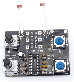
Top components
Begin by installing all the parts that go on the top of the circuit board, or “PCB”.
Use the parts list to identify the components.
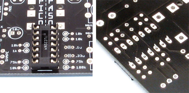
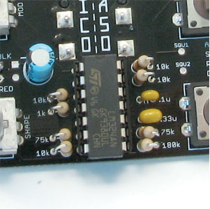
DIPs
These are sockets that protect chip from direct soldering. The chip, or “IC” will be installed after all the soldering is done.
Insert the DIP into the outlined space. Orientation of the DIPs does not matter. Bend the pins toward each other using your flat head screwdriver once they are in.
Resistors
Use the parts list to identify the values. Bend one lead of the resistor down so that the part resembles a U and insert the leads into the PCB. Then flatten the leads away from the resistor.
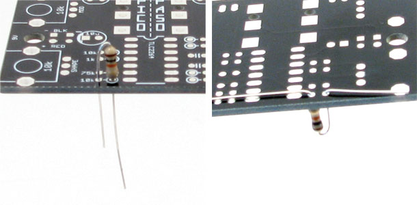
Once they are all in, clip off the excess leads. Leads can shoot off with some force so be sure to wear your saftey glasses. The best place to cut is just on the outside of the pad, leaving enough lead for the part to hang on but not too much so that it could touch another pad.
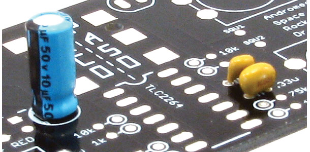
Capacitors
The small, yellowish “ceramic” capacitors are non-polar, meaning you can put them in either direction.
Put the .1uF (tan colored, marked 104 on one side) in its space, then fold and cut the leads just like the resistors.
The 10uF “electrolytic” capacitor is polar and needs to be installed in the correct direction. The shorter lead should go in to the square hole on the left side.
The space marked .33uF might contain several different parts.
If you received a cylindrical .33uF or a ceramic .33 (marked 334 on the side) put it in the space. Direction does not matter for either type.
If you did not get a .33uF you’ll have another .1uF. Put it in the .33uf space. Direction does not matter.
No matter which cap you got you’ll still be making crazy sounds!
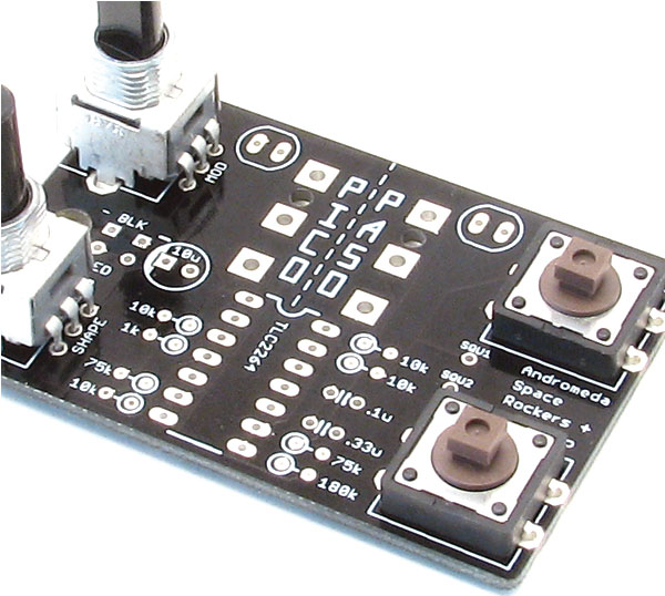
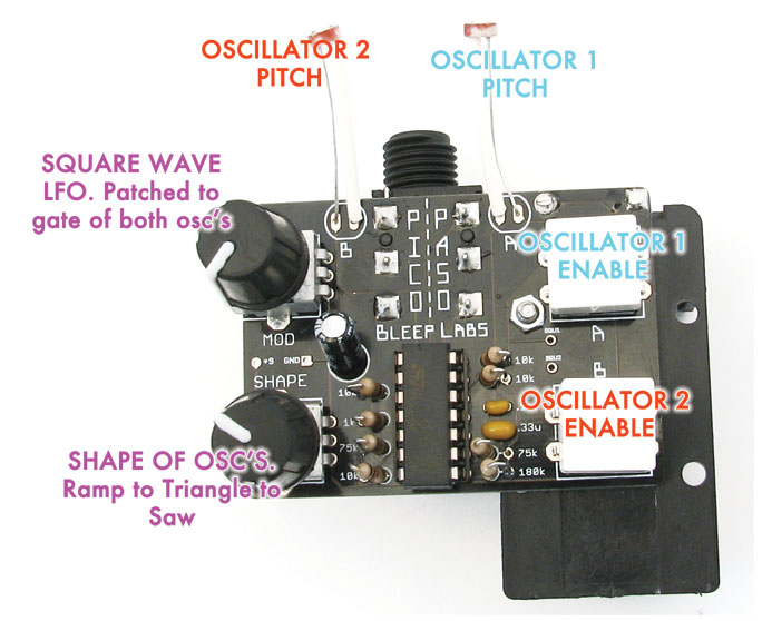
Switches and Pots
The controls snap into place. Snap the buttons into the holes on the right and fold their leads inward. The pots go on the right. Don’t worry about folding their leads. If the buttons included have little pegs on the bottm, snip them off.
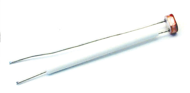
Photocells
Take the white rubber insulation and put one around a lead of each photocell. Then insert the photocell into the holes at the top of the PCB. Direction does not matter.
////////////////////////////////////////////////////////////////////////////////////////////////////////////////////////////////////////////////////////////////////////////////////////////////////////////////////////////////////////////////////////////////////////
Soldering
Once all the top components are in the correct places and their leads are trimmed, it’s time to solder.
With all the top side components in. it’s time to solder. First check if everything is in the correct places.
Before you solder make sure that your soldering iron is in good shape. If your tip is torn up, you might destroy the pads. The tip should be clean, shiny and not have any craters in it. If you’re unsure if your iron is the right type or if you have any other questions about soldering, see our soldering 101 page.
We soldering, remember to heat the part then push the solder into the joint. Don’t try and “paint” the solder on.
1 – Heat the part for 2 seconds.
2 – Push in just enough solder to cover the joint
3 – Remove solder but continue heating joint for 2 seconds.
First, solder the switches and pots. Make sure the part is perpendicular to the board before you solder it.
Next just work in lines from top to bottom so you don’t miss any pads or connect any leads together.
////////////////////////////////////////////////////////////////////////////////////////////////////////////////////////////////////////////////////////////////////////////////////////////////////////////////////////////////////////////////////////////////////////
Bottom components
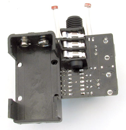
1/4” Jack & Battery holder
With the bottom soldered you can install the rest of the components. Insert the 1/4” jack and 9V holder from the bottom and solder them in place on the top side of the PCB.
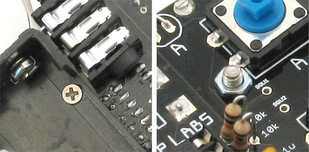
Battery holder screw
Take the tiny screw and push it through the 9V holder and PCB from the bottom then screw its nut on the top side. Use pliers to hold the nut in place and tighten the screw.
////////////////////////////////////////////////////////////////////////////////////////////////////////////////////////////////////////////////////////////////////////////////////////////////////////////////////////////////////////////////////////////////////////
Testing
Time to try it out!
Snap the button caps on the buttons and the knobs on the pots. Insert the chip into the DIP with the notch facing up as shown. The PicoPaso turns on automatically when you plug a mono 1/4” cable in to it. A stereo cable will not turn it on.
You should be hear noise the instant you push one of the two buttons. If it doesn’t come on immediately remove the battery and :
– Turn the MOD knob. There might not be any sound when it is turned all the way in either direction.
– Check that the chip is inserted in the correct direction.
– Look for bad or unsoldered pads.
– Make sure your amp is working and that the cable is mono. The device will not turn on with a stereo plug.
If you’ve checked all the components and reheated all the solder joints the best advice is to come back to it later. Seriously! I cannot count the number of times I have spent hours infuriated by a project, only to look at it the next day and find the problem immediately. If you still have problem, feel free to contact us at drbleep@bleeplabs.com
////////////////////////////////////////////////////////////////////////////////////////////////////////////////////////////////////////////////////////////////////////////////////////////////////////////////////////////////////////////////////////////////////////
Modifications
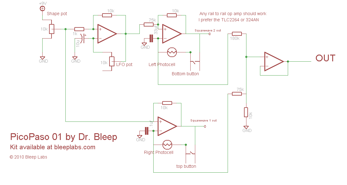
The SQU1 and SQU2 pads are square wave outputs of both oscillators (as opposed to the triangle wave outputs going to the 1/4″ jack).
The capacitors control the rate of the oscillators. .1 for “A”, .33 for B, and 10uf for the LFO. Change these out with different values to change the pitch ranges.
______________________________________________________________________________________________________________________