This project can be completed by those who are new to soldering, but it is very important that you know how to solder safely before you start. This includes working in a well-ventilated area and wearing safety glasses.
Check out bleeplabs.com/kits for more info about tools and videos on soldering properly.
______________________________________________________________________________________________________________________
Begin by installing all the parts that go on the top of the circuit board, or “PCB”.
Use the parts list to identify the components.
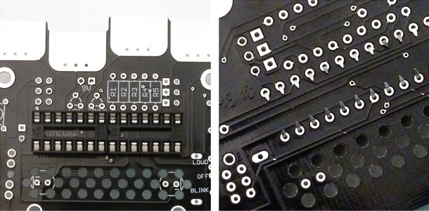
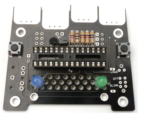
DIPs
These are sockets that protect the chips from direct soldering. The chips, or “ICs” will be installed after all the soldering is done.
Insert the DIPs into the outlined spaces. Orientation of the DIPs does not matter. Bend the pins toward each other using your flat head screwdriver once they are in.
______________________________________________________________________________________________________________________
78l05 and NPN
The 78l05 will have straight legs while the NPN’s are bent. Bend their leads out slightly so they fit into the PCB and push them down almost all the way.
Make sure they are in the correct direction before you clip the leads. Leads can shoot off with some force so be sure to wear your safety glasses. The best place to cut is just on the outside of the pad, leaving enough lead for the part to hang on but not too much so that it could touch another pad.
______________________________________________________________________________________________________________________
Resistors
Bend one lead of the resistor down so that the part resembles a U and insert the leads into the PCB. Then flatten the leads away from the resistor.
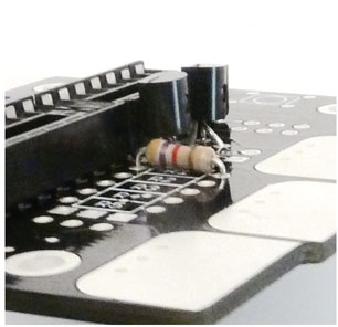
Once they are all in, clip off the excess leads as before.
______________________________________________________________________________________________________________________
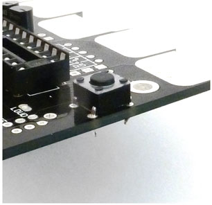
Buttons
Snap the two buttons in but be careful not to push them into your finger on the other side!
______________________________________________________________________________________________________________________
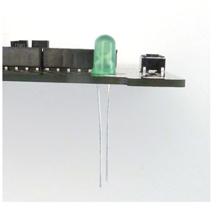
LEDs
The short lead of the LED should go into the square pad.
______________________________________________________________________________________________________________________
Once all the top components are in the correct places and their leads are trimmed, it’s time to solder.
With all the top side components in. it’s time to solder. First check if everything is in the correct places.
Before you solder make sure that your soldering iron is in good shape. If your tip is torn up, you might destroy the pads. The tip should be clean, shiny and not have any craters in it. If you’re unsure if your iron is the right type or if you have any other questions about soldering, see bleeplabs.com/thingamagoop2 for more info.
We soldering, remember to heat the part then push the solder into the joint. Don’t try and “paint” the solder on.
1 – Heat the part for 2 seconds.
2 – Push in just enough solder to cover the joint
3 – Remove solder but continue heating joint for 2 seconds.
First, solder the switches and pots. Make sure the part is perpendicular to the board before you solder it.
Next just work in lines from top to bottom so you don’t miss any pads or connect any leads together.
______________________________________________________________________________________________________________________
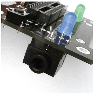
1/8″ Jack and Switch.
Snap the jack into the bottom as shown. The switch goes in the opposite side. Make sure they are fluch to the PCB and solder them up.
______________________________________________________________________________________________________________________
9V snap and Speaker.
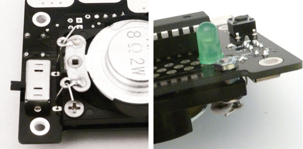
Clip the 9V’s wires to about 4″. Mount two screws into the speaker as shown. Thread the 9V’s wires in and insert the assembly into the front PCB.
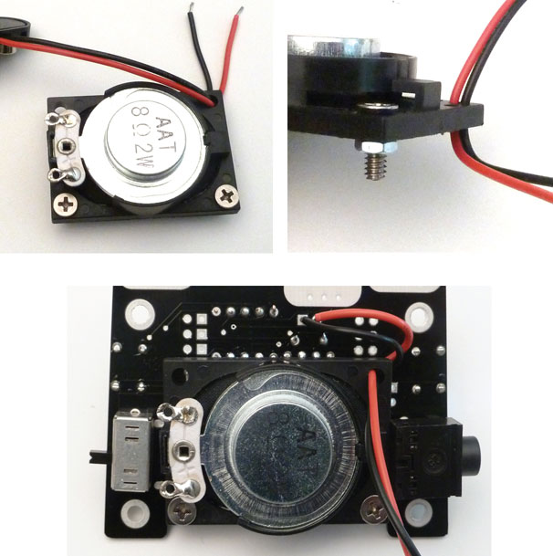
Screw the assembly to the front. Use two small lengths of wire or leftover leads from the resistor to attach the speaker’s pads to the PCB. Then solder the 9V wires to their pads above the 78l05. red wire in the round pad, black in the square.
______________________________________________________________________________________________________________________
It’s time to test it out! The back doesn’t have to be attached for the Jr. to make noise. Just insert the chip with the writing right side up.
You should be hear noise the instant you turn it to “LOUD”. If it doesn’t come on immediately remove the battery and :
– Check the battery wiring.
– Check that the chip is inserted in the correct direction.
– Look for bad or unsoldered pads.
If you’ve checked all the components and reheated all the solder joints the best advice is to come back to it later. Seriously! I cannot count the number of times I have spent hours infuriated by a project, only to look at it the next day and find the problem immediately. If you still have problem, feel free to contact us at drbleep@bleeplabs.com
______________________________________________________________________________________________________________________
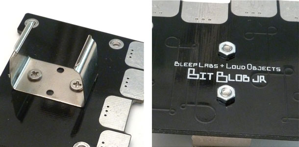
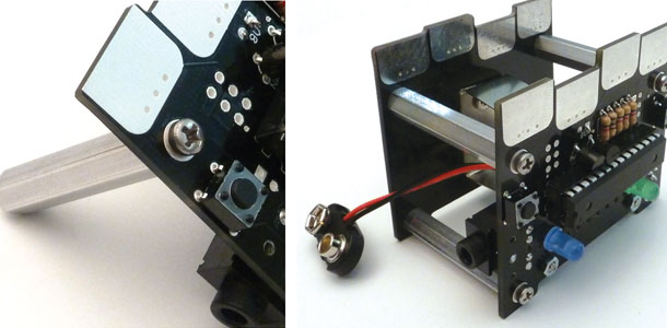
Rear PCB.
Attach the battery clip and standoffs as shown. The standoffs connect the front PCB to the back so no wiring is needed.
______________________________________________________________________________________________________________________
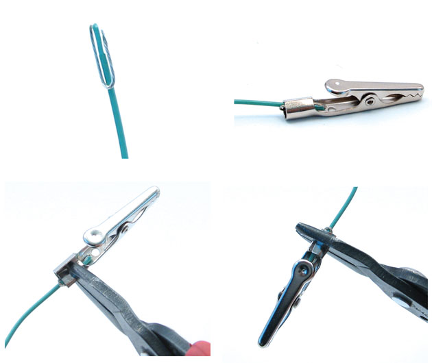
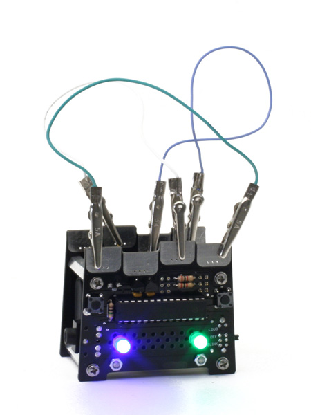
Patch Cords.
The last step is to build three patch cables. Strip about 1/4″ off the ends of all the wires then loop it around as shown. insert the stripped end into the alligator clip and use your pliers co clamp down one side of the barrel, then the other.
______________________________________________________________________________________________________________________
Connect and of the eight pads together to create digital madness. Hold the buttons to change the pulse width. “BLINK” mode outputs through the 1/8” connector but not the internal speaker.
Have fun making noise!
______________________________________________________________________________________________________________________
![]()