Instructions for original Bleep drum kit (Pre 2020)
Before you begin, check out the soldering guide for more info about tools and videos on soldering properly.
______________________________________________________________________________________________________________________
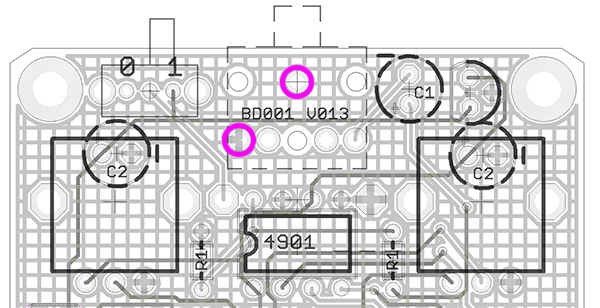
The first components to go in are the three capacitors. Insert them into the three dashed circles from the bottom with the short legs in the holes marked with a ” – “.


Flatten the leads on the board then clip off the excess. Cut the legs so they are just on the outside of the pads. Too short and the will fall out. Too long and they might touch another pad and cause a problem.

______________________________________________________________________________________________________________________
Solder the three capacitors in.


If you aren’t yet comfortable with soldering, take a minute to looks at our soldering guides.
______________________________________________________________________________________________________________________
The DIP sockets go in next on the top side. The chips go into these at the end. The two 14 pin DIPs go in the space marked “328”. The 8 pin goes in “4901”.
Use a flathead screwdriver to flatten the pins inwards on the bottom side.


______________________________________________________________________________________________________________________
Install the large colored buttons in their places and flatten their pins just as you did with the DIPs.


The small buttons go in just the same. Be careful not to have your finger on the opposite side of their holes when you push them through! Flatten the pins just like before.

______________________________________________________________________________________________________________________
Next is the RGB LED. It goes in with the flat side on the left as shown on the board.

______________________________________________________________________________________________________________________
Bend the 5 blue, 1k resistors and insert them into the board in the five places marked “R1” Bend and clip the leads as before.

______________________________________________________________________________________________________________________
The black 78l05 and tan resonator go in as shown here. Bend and clip their leads.

______________________________________________________________________________________________________________________
The last components to go in on the top are the potentiometers. Before installing them, make sure that the capacitors installed on the bottom are in correctly as they cannot be redone after the pots are in. You do not need to bend and clip the pots leads.

______________________________________________________________________________________________________________________
Soldering
Before you begin, make sure that all of the components are in the correct places and that none of the leads are touching. Once you’re done, clip off the pots’ pins. Make sure every pad on the bottom is soldered.
If you get some unsightly brown dots and want to get rid of them, wait 15-30 minutes for them to dry. Then carefully scratch them off with a plastic disposable knife.

______________________________________________________________________________________________________________________
Once the bottom is fully soldered, there are just a few things left to do before you can make some boomclappoonnnchpewwwwwss.
Insert the 1/8” jack and the slide switch from the bottom side. Fold the outside pins of the switch outward with your screwdriver.

______________________________________________________________________________________________________________________
Last is the battery holder.
If yours has pins follow along here:
Use your pliers to pop and bend the pins out of the plastic so they look like this.


Install the battery holder into the pads on either side of the 8 pin DIP.

Before you solder the pins, take one of the small screwdrivers. Hold it against the battery holder as shown and tighten a nut on the other side. Do the same with the other small screw on the other side of the 9V holder.


Now solder the pins.
Make sure the battery holder is as flush to the board as you can get it. This is best achieved by holding down the board on the table while soldering the pins.

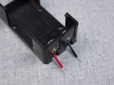
If your part has wires:
Clip and strip the wires down to about this length.
Insert the wires into the into the pads on either side of the 8 pin DIP.
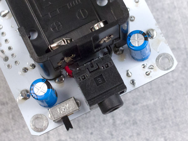
Before you solder the wires, take one of the small screwdrivers. Hold it against the battery holder as shown and tighten a nut on the other side. Do the same with the other small screw on the other side of the 9V holder.
Now solder the pins.
Make sure the battery holder is as flush to the board as you can get it. This is best achieved by holding down the board on the table while soldering the wires.
______________________________________________________________________________________________________________________
Install the chips. Gently squeeze their pins towards each other so they fit into the sockets.
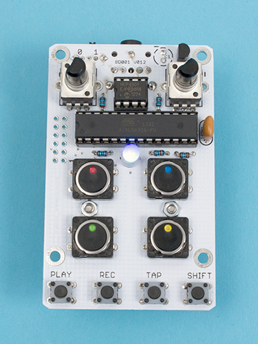
Make sure the text is right side up and that the notch is on the left. Put a battery in and turn on the switch.
Success! You now have a functioning beat-machine!
______________________________________________________________________________________________________________________
Troubleshooting
The Bleep Drum has a phased stereo output. The tip is the signal, the ring is ground and the sleeve is not connected.
This means that headphones are in stereo and sound huge but if you want to hook the device up to an amp, mixer, or any other device you need a mono cable. Computer speakers will not work unless you use a mono adapter or solder together these two pads.
If you’re having problems with it:
– Are the chips in the correct direction?
– Is the battery dead?
– Do all the solder point look like they do in our soldering video? It’s not enough for there to just be some solder on them. Large blobs of solder might not be conducting properly. You should not be able to see the pad.
If it doesn’t come on and you’ve checked everything a couple times, the best advice is to come back to it later. Seriously! I cannot count the number of times I have spent hours infuriated by a project, only to look at it the next day and find the problem immediately.
If you still have problem, feel free to contact us at drbleep@bleeplabs.com
______________________________________________________________________________________________________________________
If you’re installing a MIDI board, go here.
If you have standoffs follow along with this guide.
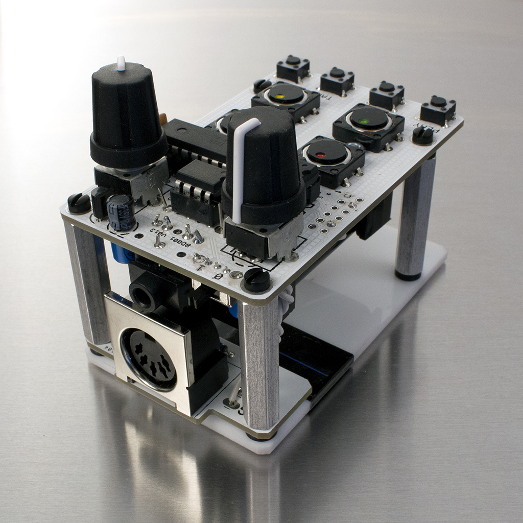
If you have an older version withscrew legs, go here.
______________________________________________________________________________________________________________________
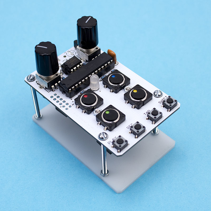
Mount the bottom plate by first removing the brown paper mask. Then install the black plastic screws and standoffs as shown. Take care not to over tighten them.
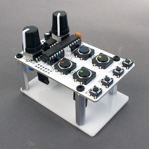
Congratulations! Go make some noisy beats!